![]()
![]()
![]()
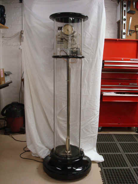
Maker, Warren Telechron, Inc., Ashland, Massachusetts, USA. Model Type E, c. early to middle 1930's, serial no. 17. Originally set up at the Tennessee Valley Authority (TVA), to control the 60 cycle frequency of the generators across the TVA power grid. One second pendulum (Invar) with separate magnetic control rate trimmer. Designed to be operated under partial vacuum. 59"h, base 20" diameter, glass tube 49.5" x 10.5" diameter.The word Telechron is a composite pair of words from the ancient Greek: Tele = to or at a distance, and the Latinized Greek word Chronos, chron = time. Time over distance. The perfect description of a master clock.
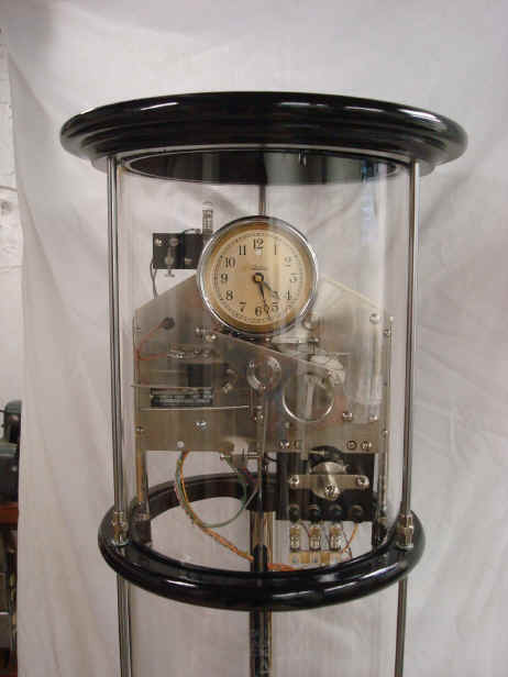
Much of the movement as well as the metal used in the enclosure are made from aluminum. This example contains automatic time error correction through a series of servo motors, switches, levers and cams that detect the rate of the pendulum and adjust themselves to it. The automatic feedback control is accurate 1/400th second. Telechron's first model, the Type A required an operator to observe the difference and initiate changes manually. It appears that the Type E had a very limited production and little is known about it. Only two other intact examples are known, those are from the Hoover Dam; now in permanent storage at the dam site and unavailable to view. I know of five other non-working examples: s/n 11, located in the Eastern US, s/n 14 in a power house in Maine, s/n 28 formerly used in the Imperial Irrigation District, Imperial, CA - it is missing the entire metal and glass encapsulation, s/n 18 that has all of the glass tank damaged beyond repair, and one from a dam in Uruguay, condition unknown. If anyone knows of further examples please do contact me. Click here for patent drawings and installation manual. A short history of the Telechron company and it master clock product line is in the section describing the Type A.
Click on the picture to go to a page for more detail.
Why was this clock made in such small numbers as opposed to Telechron's prior, highly successful models A and B? One can only speculate but I submit a few reasons based on my experience with this artifact and the context of the times when it was launched. First, this was introduced during the Great Depression, so any new product launch would be severely crippled, even by a firm and inventor as renown as Henry Warren and his Telechron company. Second, Warren's design, while incredibly ingenious suffered from complexity and fast moving parts. Whereas the competition relied on precision machining and perfect execution (Reifler, Shortt). Warren's movement was, an 'erector set' quality in comparison. He made up for this with his ingenious frequency feedback control system, but nonetheless, it required a great number of rapidly moving components. A master clock must be able to run for long periods of time undisturbed to achieve a good rate of accuracy and Warrens design precluded this. Perhaps this was not an issue in the narrow scope of power house frequency control, but I doubt it. The fact that the clock was meant to be sealed in a partial vacuum indicates that had to be reliable for long periods of time which, in my opinion, was impossible using this design. There is evidence that this clock was actually used in some field applications. This example is said to have been taken from the TVA Authority dam operations.
Below are two photos of the Telechron E both in field locations which seem to contradict my conclusions above. The first is from a technical publication dated 1941 by the Leeds and Northrup Company titled Load-Frequency Control for Interconnected Power Systems. In that manual they state, "One type of time standard is shown in Figure 10 which is the Warren Type E pendulum clock now widely used in central stations for this purpose." The second a 1941 advertising flyer from the Telechron company indicating that a pair of Type E's were used at Boulder Dam, now named Hoover Dam, and had been in good operational service for five years. The photo referred to in the Leeds manual also pictures a Type A which indeed, was in widespread use in power stations at that time. If these two pieces of evidence are to be believed why the lack of any examples other than the two known are extant? We know the Type A was used in over 80% of the power station for frequency control in the late 1930's through the mid 1950's and there are scores of examples to be seen. Anyone who can shed some light on this please do contact me.


The first photo above is of the very successful Type A frequency control master clock. The second photo shows Henry Ellis Warren, the inventor of the self-starting synchronous motor, the heart of his master as well as domestic clock designs. Until the late 1940s, station clocks from the Warren Telechron Co. regulated over 95 percent of all U.S. electricity lines.


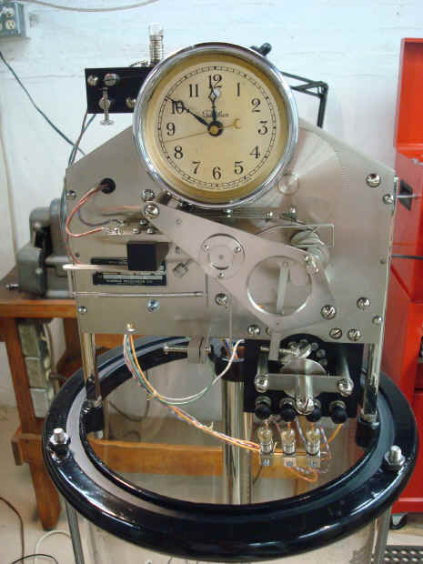
The first video shows the front view. The three incandescent lamps are not an original feature but was put in to demonstrate the output of the commutator. The combination of electrical output would be used to control a device to regulate the generators in a power plant or other device. Very similar to the function of a governor. In the second video one can see the epicyclical wheel rotation and in the third it's rotation in step with that of the commutator. The epicyclical wheel is tied into the regulation of the clock's dial while the commutator sends the same motions as electrical commands for remote control. The fourth and fifth videos show the frequency sampler driven by a rotating cam and delivered via a set of stepped contacts to the bi-directional motor connected to both the epicyclical wheel and commutator. Last two show an overall view of the clock before and after restoration. It should be noted that under normal operating conditions the bi-directional motor and thus the epicyclical wheel as well as the commutator would move quite seldom. After all adjustments are made and the system has time to settle, the line frequency and the pendulum would generally be in agreement. I have purposefully upset this equilibrium for purposes of this display.
![]()
![]()
![]()