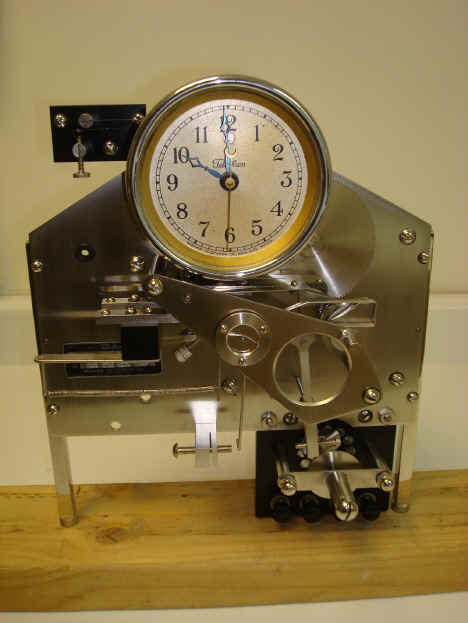
Maker, Warren Telechron, Inc., Ashland, Massachusetts, USA. Model Type E, c. early 1930's, serial no. 17. The restored movement is shown before being installed and wired in. Notice in the second photo the circular aperture in the dial face just below the 12 o'clock position. This was present in many of Henry Warren's domestic electric clocks as a warning indicator in the event that the clock had lost power. If there was an interruption a magnetically held flag would be released behind the dial aperture giving the opening a red color; warning the observer that the time was in error. Clearly Warren had simply taken a dial from his domestic clock stock to incorporate in this movement. The entire flagging mechanism is eliminated and a simple piece of metal is glued behind the aperture. Even the dial's numerical design and hands are out of step with the rest of this clock's design. It's curious that Mr. Warren would not make a dial for this application considering that this was not a cheap clock. Why scrimp on the dial - a component that the customer would first notice? This same anomaly is seen on the file photo of the prototype clock taken in January 1930 as depicted in the NAWCC Bulletin, August 1991, page 392 as well as the only other known example. Perhaps it was thought that in a greater production run a custom dial would be incorporated, but considering the fact that not many were made, it never happened.
All of the movements components are finished in a brushed silver surface. Another nod to the art deco look that was incorporated into the case. The underlying material is of several metals. The main movement plate and front triangular subsidiary plate are steel. The secondary rear plate upon which the motors are mounted is aluminum. All of the train wheels are brass with the exception of the large epicyclical wheel and its components which are aluminum.
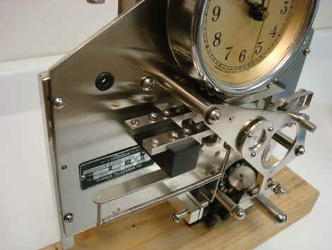
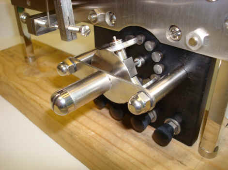
The first photo below is of the differential gear system that coupled with the commutator shown in the second to the last photo translated Warren's patented frequency regulation system into an output that could control a specialized motor or other actuator to accurately control the frequency of a power system. The next and last photos show some of the complex cam and lever works that comprise the automatic frequency regulation.
The circular porthole glass which has a crack, is yet to be replaced. It acts as a dust cover protecting the knife edge suspension upon which the pendulum impulse and frequency sampler is mounted. The rest of the critical moving components move in hard plastic pivots. These require no oil and are suitable for this application since there is negligible torque on the wheel and cam components; unlike a conventional clock where there are very high forces in the lower end of the train which would tear up such pivots in a short time.
The armature pictured below is a commutator that can rotate in either direction or be paused, depending on the corrective current impulses from the frequency sampler as dictated by the pendulum. It transforms them into proportional rotative motions in the commutator which distributes these movements electrically to various indicators or controlling devices, mainly Warren's patented rotation reproducing motors which were used to control the generators in power stations. View the videos to observe this in action.
The first video shows the front view. The three incandescent lamps are not an original feature but was put in to demonstrate the output of the commutator. The combination of electrical output would be used to control a device to regulate the generators in a power plant or other device. Very similar to the function of a governor. In the second video one can see the epicyclical wheel rotation and in the third it's rotation in step with that of the commutator. The epicyclical wheel is tied into the regulation of the clock's dial while the commutator sends the same motions as electrical commands for remote control. The fourth and fifth videos show the frequency sampler driven by a rotating cam and delivered via a set of stepped contacts to the bi-directional motor connected to both the epicyclical wheel and commutator. Last two show an overall view of the clock before and after restoration. It should be noted that under normal operating conditions the bi-directional motor and thus the epicyclical wheel as well as the commutator would move quite seldom. After all adjustments are made and the system has time to settle, the line frequency and the pendulum would generally be in agreement. I have purposefully upset this equilibrium for purposes of this display. Telechron_E_vid1.MPG Telechron_E_vid2.MPG Telechron_E_vid5.MPG Telechron_E_vid3.MPG Telechron_E_vid4.MPG Telechron_E_vid6.MPG Telechron_E_vid7.MPG
|