|
Consolidated Time Lock Co., Cincinnati, Ohio - Dalton Concussion and Calendar Timer The purpose of the concussion unit was to offer a way to override the time lock in case of its complete failure. An explanation of the function of the concussion unit and a video is found below later in this page.
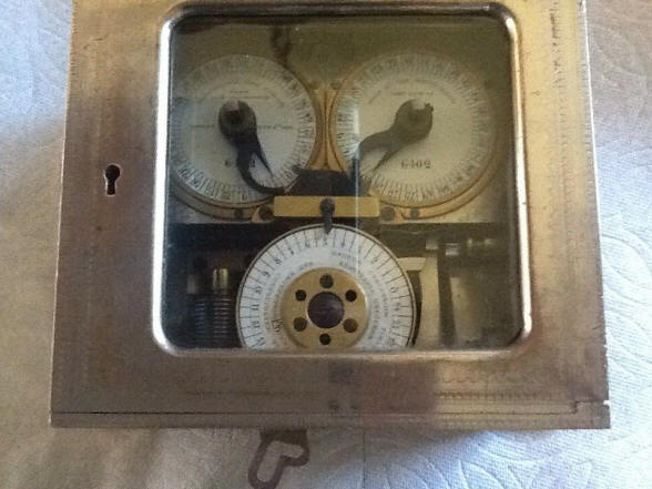
The movement on the right is the time lock. It is operated in a rather unconventional way. The back of the dial has a spiral groove into which a pin is inserted and is guided by the spiral groove, that pin being attached to the lever seen in the upper right hand corner, (see patent drawings below). The spiral is of a sufficient length to allow the forty-eight hour dial to wind to a duration of seven days. There are forty-eight threaded holes in the rim of this dial through which a 'cheese head' screw can be secured. In this photo there are two of these placed 24 hours apart so that one will engage the date wheel located in the lower middle of the lock once every twenty-four hours. This would be the most common arrangement as it allows the lock to go off guard at the same time once daily. However, there are many other patterns and hours of operation that can be achieved using different placement or numbers of pins. To the best of this author's knowledge the only other dial that has this pin-and-hole arrangement for the setting function is found on two other of Milton Dalton's locks the Dalton Dual Guard and the Dalton Triple Guard and Permutation Combination Lock, the latter which contained the Dual Guard along with an additional permutation lock. Notice there is no pointer on the dial to indicate a starting point. The dial is meant to be wound until it stops, that is when the pin in the spiral groove has reached the end of the groove where it terminates near the outside edge of the dial. Then one counts the number of open holes from the edge of the calendar wheel to equal the number of hours the safe is to be closed. On a daily basis during the week the calendar wheel is set to '1' and when the number of hours has passed the lock will go off guard. If one needs to skip a day, set the calendar wheel to '2'. If for Saturday and Sunday then set it to '3'. Longer periods can be had with the remaining dial settings. When a pin contacts the calendar wheel it will move one seventh of a turn and this is controlled by the spring-loaded roller lever at the 11 o'clock position of the calendar wheel dial as it falls into each recess of the calendar dial. The release hook will remain in the on guard position and is unaffected as the calendar wheel turns until it reaches '1', At that point the wheel will draw the hook back to the off guard position. That hook could be either used to hold the fence in a combination lock, as was commonly done with Hall/Consolidated time locks or it could be used to release an automatic bolt motor to withdraw the safe bolts thus opening the safe without the need for a combination lock and its dial as well as the manual bolt retraction lever; all of which would be outside the safe door and offering a potential way for skilled safe crackers to force the safe open. The movement on the left is the clockwork mechanism that is designed to override the time lock should the timer movement fail. Time lock overrides were generally used when there was only one time lock movement being used; offering no redundancy as found in two or more independent movements so the failure of that one movement was very real. The Consolidated Company and its predecessor, the Hall Safe and Lock Company specialized in single movement designs offered in a line of single movement time locks This gave the company a price advantage over the competing locks that used an extra movement for redundancy. The company perfected an override system known as the Infallible Lockout Protection System. This lock's override is different from their infallible design. Here the clockwork will run until it achieves the override by moving the hook to the left, off guard position. This is activated by a shaft that is next to a lever device on the lock's override and runs to the back of the safe. A single blow with a heavy hammer will cause the shaft to bump the lever, activating the override clockwork mechanism, see photos below. Like the infallible design the override is defeated if the timer portion of the lock is running, preventing the lock from being overridden when it is functioning properly. It is rare to find an override system with a lock that has the redundancy offered by two movements, but Consolidated did offer such a model with two movements in their Dalton Triple Concussion Timer. Holms is another company that employed an override with two movements. The Hollar Company used the opposite philosophy that was to keep a time lock wound indefinitely past the time it would normally be set to go off guard in case the owner would want to keep the safe closed, say in the case of civil disturbance.
The calendar wheel is shown on the bottom middle of the movement. This allows the lock to be on guard for a maximum of seven days. The other time locks that had this feature were the Mosler Calendar time lock, it featured Phinneas King's calendar mechanism first patented in 1878, improved and again patented in 1891 and appearing in that model for the first time. In additional to the conventional ability to go on or off guard daily, his model was also able to lock and unlock during the course of the day, much like the Yale Single and Double Pin Dial lock and the Holms Electric. But unlike the Yale and Holms, it also had the calendar function. The only other time lock I know of that combined all three functions was the Edward Stewart time lock. The calendar mechanism is based around the seven day dial allowing the lock to be adjusted to pass over its daily open periods for as long as the movements had reserve power, allowing for Sundays, bank holidays or other planned closures.
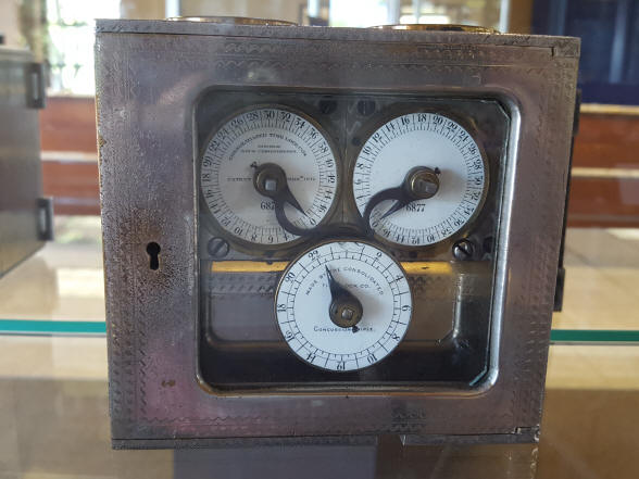
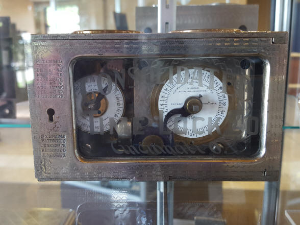
The front and rear upper three-quarter elevation.
The first photo shows the top elevation. The empty hole and platform design for the timer movement is examined below. One can see both springs, with the timer spring being even larger than the ant-lockout clockwork spring. This is needed as the timer is a calendar lock and designed to run just over seven days and is reinforced in the second photo which compares a regular single movement Consolidated lock designed to run for forty-eight hours.
The first photo illustrates two early designs for the balance wheel and escapement wheel cocks ¹. The upper caption with the 'comma-shaped cock for the escapement wheel was used on only a few of the first movements made in when time locks were being made under the Hall Safe and Lock Co. before it separated its time lock business in 1880. The configuration in the lower caption shows the next iteration used for a year or so beginning in 1876 until the movements were no longer silvered and had their underlying brass color instead. This design remained with minor shape changes for the balance wheel cock for the rest of the production run of movements having the escapement mounted horizontally on the top, also known as a 'carriage clock' design.Notice the hole that would have had the screw to secure the comma-shaped escapement wheel cock is still there and is threaded. Apparently the movement plates were already fabricated when the change in the escapement wheel cock design was made. Notice that this is an exact match to the plate and cock design for the timer movement in this concussion lock. The movement has an unevenly hand stamped number 350 in the area just below the escapement wheel cock. There are no other serial numbers found on the rest of this or the clockwork movement of the anti-lockout device. If this lock was made about the time it is illustrated in the 1893 patent, then this movement was salvaged from a far earlier production run that would have been around 1876-77. The number of 350 on the movement plate, and the number on the dial which is close at 364 backs this up. The dial says there is a patent dated June 11. 1887 but I have not been able to locate it. This is also the same patent date on a dial for the Dalton Triple Concussion timer. This author has run into other instances where a patent date is claimed and it cannot be verified. The second photo shows the concussion lever that will release the override clockwork mechanism. On the front movement plate is mounted a demonstration/test knob that will also release this same lever via the brass piece allowing the operator to check the override mechanism.
These two illustrations are from Milton Dalton's patent 508,902 dated November 14, 1893. The concussion lock is described in some detail including the spiral groove behind the dial, pins on dial rim, clockwork override mechanism, calendar wheel, override defeat device mechanism, fly governor.
In this illustration the lock is shown in situ controlling what looks to be an automatic bolt motor device. The patent spanned ninety drawings and thirty-seven pages of text making ninety-four patent claims. What is interesting is that the title page for this patent is "Method of and apparatus for controlling and utilizing concussion and applying it to safe locks." Nowhere does the tile refer to time locks. Every other patent I have seen from this and other inventors when the subject matter was the invention or improvement to safe time locks had the words "Time lock" in the title heading. This patent has, fact many methods of using concussion as well as electromechanical means to actuate a time lock override and it features several different time lock designs, this one as well as one very similar to the Dalton Triple Concussion timer, the Dalton Dual Guard, which was introduced in 1884, and others that may or may not have ever been built. Perhaps the way to address the dilemma of the example being examined here having a movement that is clearly from the 1876-77 period is that this patent was not actually addressing any time lock invention, but the various ways concussion could be used in conjunction with time locks already invented by Dalton to effect an override of a time lock. If this supposition is to be proved, patents that concern only this and the other existing concussion time locks need to be located, although the appearance of the Dalton Dual Guard certainly exposes some time line problems. There are four known concussion time lock designs by the Consolidated company and are seen below. I have yet to find a patent that illustrates any of these individually *.Perhaps John Erroll best described this patent in his book American Genius as follows: "Milton Dalton was one of the most brilliant bank and time lock designers of all time and was awarded numerous patents that he assigned to Joseph Hall's companies, (later Consolidated). In 1893, Dalton patented what seems to have been his last contribution, the Concussion Triple. This magnum opus was a time lock whose patent alone spanned ninety drawings and thirty-seven pages of text making ninety-four patent claims, (patent #508902). The Concussion Triple was the last unique device in the development of time locks and marked both the culmination and the twilight of non-modular time locks. From this point forward, the lower costs of maintaining and repairing modular movements would spell the end of built-in mechanisms". No physical example exists for this last patent which included the use of electromechanical devices ²." This author concurs that Milton Dalton's concussion lock was the last unique design before the advent of the modular time lock movement design, however, in my opinion Mr. Dalton's pinnacle of time lock design was his Dalton Triple Guard and Permutation Combination Lock, one of the most if not the most complex and expensive time lock made, and retailed in 1888 for over $750.00, and about $250.00 over the next most expensive contemporary time locks the Yale Model 1 Double Pin Dial and Sargent and Greenleaf Model #2.Model - Dalton Concussion and Calendar Timer, c. 1877 *. Lock has a Dalton-designed single movement timer and equipped with a clockwork concussion override unit mounted next to it. Concussion timers saw very limited production and are rare. No other examples of concussion timers, with the exception of those on this website, one sold on eBay and those in the Miller collection are known to this author, see below. 5 1/8"w x 3 1/8"h x 2 7/8"d, case #31, chronometer movement marked #350, dial #364, lockout unit without markings. file 358 The first photo below is an identical timer sold in 2019 on eBay. The chronometer movements number 6402, concussion timer A20. The difference in movement numbers from this example at 6402 to the author's example of 7001 is 599. Yet the difference between the concussion timers, assuming they were also numbered sequentially is a difference of only 7. This indicates the relative scarcity of the production run of these timers. The next three photos are other concussion models by Consolidated from the Harry Miller Collection. The first photo is identical to another on this website the Dalton Concussion Triple Timer. The second bears a resemblance to the first but has a decorative plate across the lower half of the lock. Given the mechanism in the first lock, this plate could not have fit and so the concussion timer must have been of a substantially different design. The patent drawing shown in Erroll's book on page 271 cannot be the same time shown on the prior page as the case is a not the same design. That extensive patent had many time lock iterations to demonstrate their use in concussion, many of which were probably not put into production. The other two smaller locks look to be earlier designs. The first is identical to the lock herein studied. The patent link shown on this page illustrates this type of lock and must have been a later improvement as it is dated 1893. The second one has a patent date one year earlier, 1886 and has a conventional single chronometer movement with the second a dial to the left, that probably performed a similar function to the clockwork lockout device on the lock in the photo next to it but lacking a calendar function, however without being able to closely examine this lock this is a mere speculation. At this time, with the exception of the two locks seen on this website the one off eBay, and another in a private collection identical to the second photo below, none of these designs have been seen outside of the Miller collection.
|


1. Photo credit, American Genius, John and David Erroll, pg. 169
2. American Genius, John and David Erroll, pg. 270
![]()
![]()
![]()