|
Blake's Bank Lock Inspection Co.'s Columbian time lock, Worchester, Massachusetts
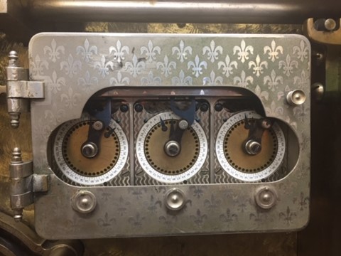
The World's Columbian Exposition of 1893 in Chicago was one of the great fin de siècle technical fairs that showcased the fruits of the industrial revolution. Along with the Exposition Universelle de Paris of 1889, the Columbian Exposition offered a stage for innovators in all technical areas to introduce their products in a high-profile arena. One of these was Blake's Bank Lock Inspection Co. of Worcester, Massachusetts. Originally, Fredrick H. Blake intended to compete with the time lock manufacturers to provide time lock maintenance services, but he secured a series of patents in the early 1890's culminating in patent #526,555 awarded September 25, 1894, for what would be named Blake's Columbian time lock after its original venue, (see patent illustrations below). Constructed under contract by E. Howard, the Columbian time lock used three seventy-two hour modular movements notable for both their broad faces and the three-plate construction. This allowed a person to reverse the direction of the time lock movement and was one of the distinguishing features of this lock. However, this ability was costly, pushing the price to $33.33 for each movement, making them the most expensive modular movements made prior to World War I. Despite the expense, Blake's Columbian was successful, offering the prestigious large-format movements found on even more expensive four-movement time locks, such as Yale's 1893 Quad N, in a three-movement design. Author's comments: Perhaps a more apt comparison would be the Triple N for automatic bolt motors, or Triple M used to dog conventional bolt work as these were closer in size; the Yale Quads that used their largest 'M-sized" movements were considerably larger. I have not seen any modular movement made after 1914 that was more expensive, if anyone has knowledge to the contrary please let me know. The fact that E. Howard Company records show seventy seven movements were ordered by Blake, between 1893 and 1897, a four year period; enough for only twenty five time locks does not, in this author's opinion qualify as a successful product. The Columbian's nickel-plated bronze case set it apart from its contemporaries in both appearance and function. The case is plain except for the door, which featured an unusually elaborate art nouveau design applied via acid etching. Blake also included a unique reversible bolt mechanism. As claimed in his 1894 patent, the boltwork connector, shown here installed to the right, could be exchanged with the threaded case plug from the opposite side, allowing the one design to engage the safe bolt work from either the left or the right. Blake's reversible bolt would be adopted, altered, and independently patented by many other makers, eventually to become the design standard. Unfortunately for Blake, he would never receive neither royalties or recognition during his time. (1)
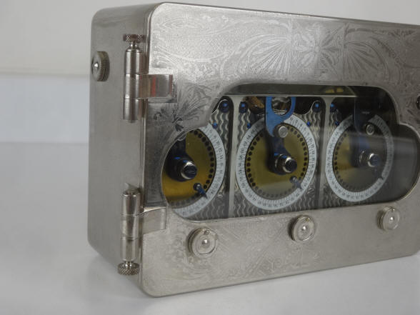
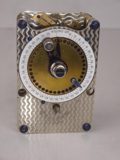
The case has an acid-etched art nouveau design design. Note the special hinge design reminiscent of a safe door hinge.
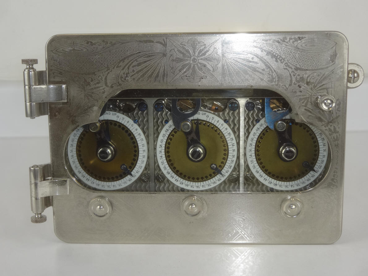
The 36-hole disk rotate a dial hand against a fixed outer dial. The only other time locks employing this reversal was the Yale Type D and Type E, and Beard & Bro. Type 1 and Type 2.
Another view of the decorative hinges. There is no other time lock case I have seen where such attention to detail has been paid to the door hinge design.
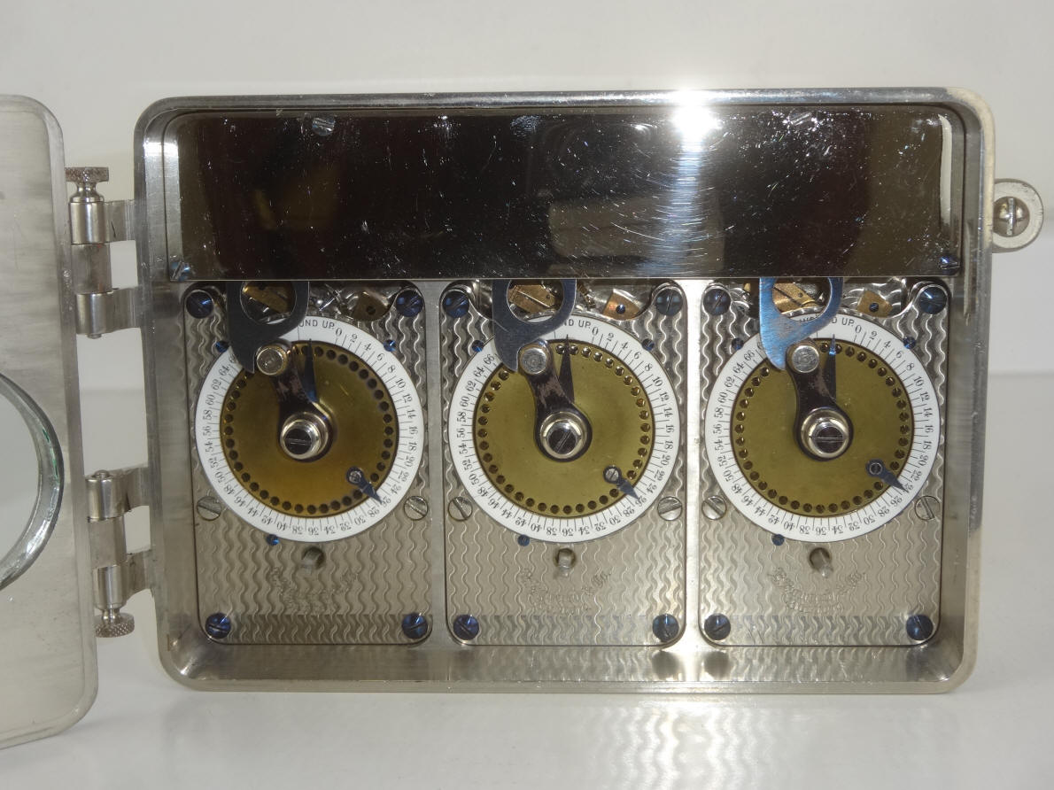
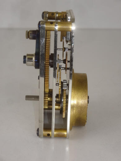
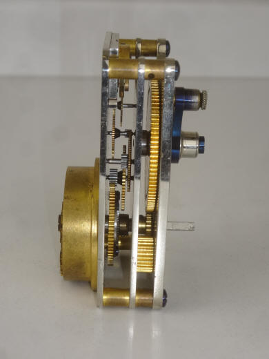
The first photo shows the E. Howard signature around the winding square. The central brass time-disk with 36 holes and a rotating armature is what turns with the time movement, the dial is fixed to the front plate. The number of hours wound up on the movement is read off the small dial pointer against the fixed dial ring. The next two photos clearly show the triple plate design needed to allow the separation of the time movement train from the components that drive the time disk. This allows one to remove the front plate and do the necessary wheel changes to make the time disk to reverse rotation (description below). Notice the platform balance and escapement wheel cocks are in plain brass in contrast to their usual gilt decorative components seen in their regular run movements supplied to other time lock makers. The only other E. Howard movements I have seen with this plain finish are the Consolidated Company's Dalton Dual Guard and in a the limited number of Type 2 time locks made for the Beard Bros. company which was later folded into the Mosler company and resulted in their Model 1 and Model 2 locks before moving on to off the shelf Illinois Watch Co. #18 size Model 4 pocket watch movements. Even so, At $33.33 each, these were the second most expensive time lock movements made for the time lock industry by the Howard company, surpassed only by the Dalton Dual Guard at $55.00. It is an interesting observation that the most costly movements put out by Howard had some of the plainest decoration in the platform assembly components.
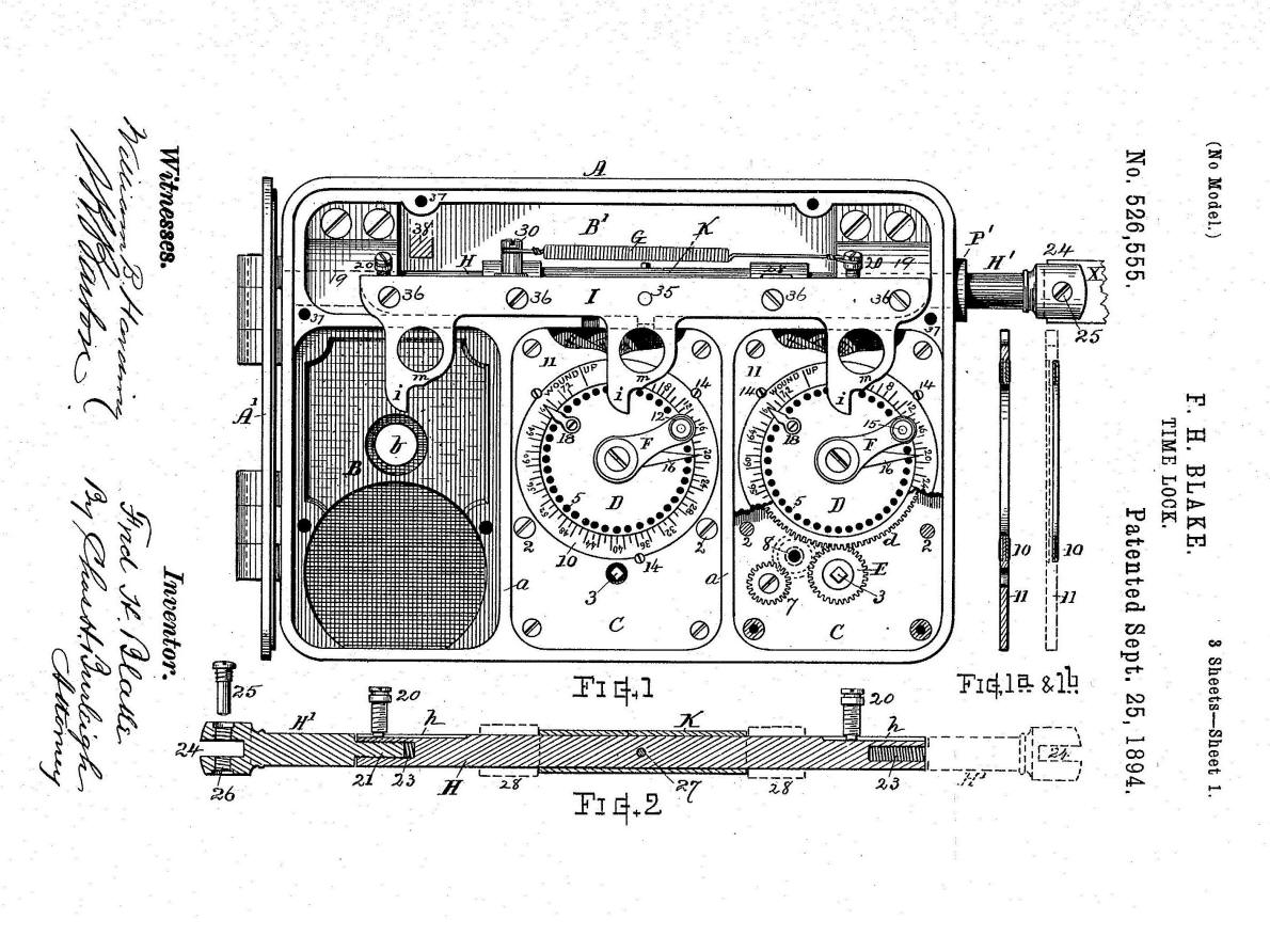
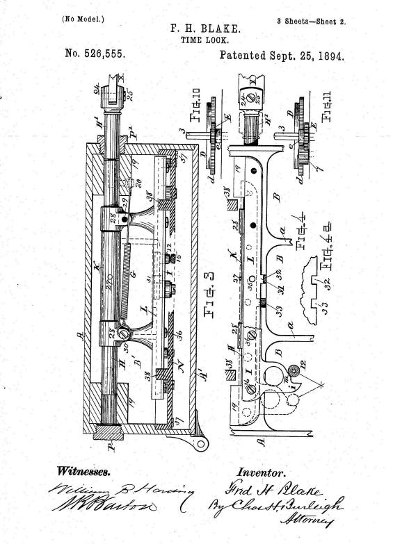
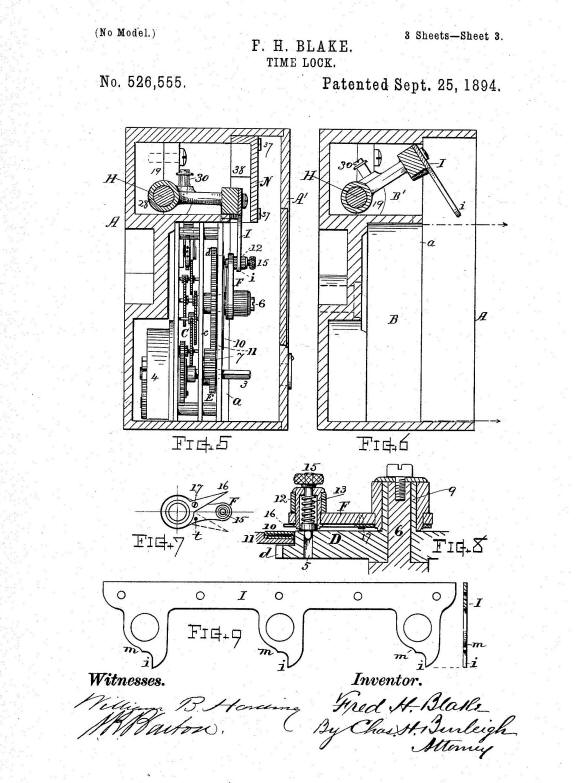
Patent illustration Sheet 1. Note how the patent illustration is virtually identical in every respect, even in all the internal components, the spring and style and position of screws, to the final production run. This is rare. Usually changes are made as the product proceeds from patent prototype to the production run stages and is an indication that Blake had made this lock before he applied for the patent, and is backed up by the fact it was displayed a year before the the patent was granted at the Columbian Exposition. An alternative possibility is that this is the patent model.
Patent illustration Sheet 2 and Sheet 3. Blake claims several innovations in his patent but the significant ones relate to his assertion that his lock was reversible. Meaning that it could be applied to bolt work on either right or left-hand hinged safe doors as the boltwork would be mirrored requiring the opening through which the bolt either slides into the time lock case or a retracting device coming from the time lock connecting to the bolt work would need to be located either on the right or left hand side of the case. To accomplish this there must be three conditions.
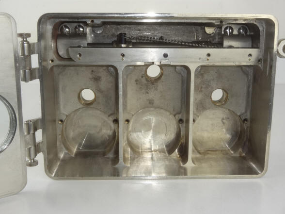
The second condition is the most difficult. Up to this point time lock makers simply made their time locks in a left and right handed version. All makers with the exception of Diebold dealt with the mirror issue by altering the snubber and dog assemblies, as well as drilling the hole on the appropriate side of the case, leaving all of the movements to to operate unchanged in one direction. Diebold issued movements that rotated in both directions making clear warnings necessary to technicians replacing movements to be sure the correct directional movement was being used. It's hard to understand why Diebold took this route since one still must alter the hole position in the case and the boltwork still had a mirrored design. While it would be possible to simplify the bolt dogging mechanism with a reversible time lock movement, Diebold still chose to make custom mirrored dog and snubber bar assemblies. It appears that Blake was trying to create a lock that could be made reversible in the field. I have reversed the bolt dogging mechanism in the lock and while not easy, it is straight forward, every step of reassembly must be in the exact order. The lock came with a decorative plug for the unused case hole. The reversal of the time lock movement is quite ingenious, but again is not something anyone can do, and here is where the unique and expensive triple plate construction comes in. Referring to diagram Sheet 2 of the patent Blake explains "Thus when the time lock is for right hand action the gear is placed on the (square, winding) arbor with its toothed portion to the front, (see Fig.10) and its teeth engage direct with the time-disk gear; but when the time lock is for left-hand action the gear E is slipped off the arbor and and replaced with its hub at the front, (it is reversed) thereby offsetting its toothed portion from the plane of the time lock disk-gear, (see Fig. 11) and the change-gear 7 is moved into mesh with the said gears by placing its stud into the hole 8, to act as an intermediate. Then the time-disk is caused to have an opposite direction of rotation as that indicated in Fig. 1" (on Sheet 1). Of course to do this one must first remove the front plate to access the time disk, winding arbor gear and change gear, but this can be done safely because the rest of the time lock movement is located between the two lower plates and so remains intact. There is no need to let down the mainspring or do any other special steps as far as the time movement is concerned. However, this is not a simple procedure. One must remove both the small dial indicator, and the central rotating hub mechanism. The dial ring must also be removed by unscrewing three very tiny watch screws and reversed, did I forget to say that this enamel ring is quite fragile? To this author's knowledge no other maker tried to make an "in the field" fully reversible time lock. Another interesting innovation claimed by Blake is seen again on Sheet 2, Fig. 4 and Fig. 4a. Here there are notches 32 and 33 seen in Fig. 4a. When the lock is on guard the bolt dog detent number 31 drops into notch 32 preventing backward forcing of the dog and thus the snubber bar to defeat the lock. As the timers wind down to zero to bring the lock off guard, a contoured section of the snubber bar comes in contact with the roller attached to each timer movement armature attached to the rotating disk and raises the detent out of the notch allowing the snubber to be pushed to the left by the timers and put the lock off guard. Notch 33 is used when the operator wants to set the time lock but still wants it off guard for some period of time. He simply moves the snubber bar to the left until the dog detent 31 drops into notch 33, thus holding the snubber in the off guard position. The design of this feature is of rather dubious use, if the operator forgets to release the snubber bar to spring back to the on guard position he will be able to close the door and the lock will remain off guard unbeknownst to him. Contrast this to the Hall Infallible Chronometric ™ device where one could set the time lock, put the lock temporarily off guard and dial in a set amount of time until the owner wanted the lock to go on guard and this would occur automatically without any further intervention needed. A visually distinguishing feature of this time lock other than the case and the movement's triple-plate construction is the rotating disk with thirty-six holes each covering a two hour period each. A rotating armature which pivots on the disk's central axis and has attached to its end a spring-loaded pin which can be raised to allow the armature to turn and then drop into a hole to lock the armature in place. To use this the operator winds the movement fully to where the small indicator hand attached to the disk aligns to the line marked "wound up". The operator then simply rotates the the armature to the number of hours he wants the lock on guard. The advantage of this system is that as long as the operator winds the movement to the mark "wound up" the opening time will always be the same until the operator changes this with the rotating armature. There are several disadvantages, the first being that the holes cover a two hour period, so the operator really cannot just wind the movement to the "wound up" mark if he needs to add or subtract an hour to the correct time. He must interpolate the time. Worse this requires one to wind the movements at the same time each day, otherwise if the armature is not moved, and one closes a couple of hours late, the lock will go off guard two hours later in the morning. The ease of use, accuracy and practicality is in all respects inferior to that of a rotating dial that one would simply set to the number of hours one wants the lock to remain on guard at the time the lock is wound. The last innovation claimed is a snubber bar that swings outward to allow the movements to be removed without having to remove any of the dogging work including the snubber bar. However, to take advantage of this feature one must still remove the four screws which holds the upper plate covering the snubber assembly so this is not mush of an advantage to the designs of Yale or S&G where a few screws will remove the snubber bar obstruction. Blake ordered at least seventy-seven movements from E. Howard between 1893 and 1897, enough for twenty-five time locks. It is not known just how many of these were assembled, but the example shown here is the only known to remain today.¹ Author's note, as of June 2024 a photo of another Blake's lock has surfaced still in situ on a safe door in South America, see photo below. Photo credit, Ryan Krakowsky. 1893. This example is the same as illustrated in American Genius is is probably the patent model for this time lock, pp. 284-285. 7 1/4"w x 5 1/4"h x 3 1/4"d. Case #103, Movement #27, #28, #29. file 200
1. American Genius Nineteenth Century Bank Locks and Time Locks, David & John Erroll, pp. 284-285. |
![]()
![]()
![]()