Finish Robin remontoire and begin lower movement main frame - September 2009
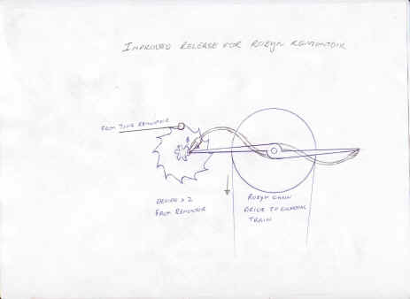
B. now finishes the Robin remontoire. The drive wheel is fully spoked out. A new detent is used in place of the 'C' shaped escapement which had too high an unlocking friction to be useful. This redesign strongly resembles that used by Bernard-Henri Wagner in his remontoire of the 1850's. In fact we use a version of his design in the time train for which I give credit to Wagner. It's interesting to see how the great horologists of yesteryear still have something to teach us today! As the saying goes, the more things change the more they stay the same. Seems like the old masters had their designs quite well refined. B will redo the detent as shown in the second drawing in keeping with the curvilinear lines of the rest of the movement. The last photo shows the drive wheel in place. View third YouTube video at the bottom of this page to see it operating.
Below are a few shots of the release lever, still the original straight design as depicted in the first drawing.
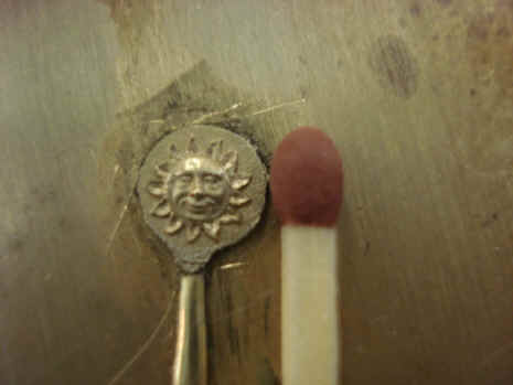
In the meantime B. is honing his engraving skills. In fact the example below is more like sculpting. This is a face that will be used on an equation hand in another clock. But it will come in useful for the equation hand on this project too. A nice older gentleman's face.
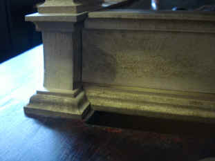
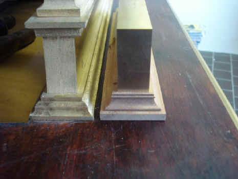
We now move into a new area of fabrication, the main movement frame. This is the realization of our redesign conceived in December 2008 and materialized in the movement mockup of last March. First several mockups were made in wood showing the type of detail we envisioned to be applied to the pillar bases, capitols and the lower, base frame moldings. Notice the end rails will be slightly coved. Third photo shows the raw stock. The darker material was stock that was stress-relieved in B's specially built furnace last May. This was done so the long bars would not slightly curl as the fly cutter was applied. Next photo shows the planing of the stock to achieve exact exterior dimensions, see movie clip below. The next two photos show the first rough stock assembled.
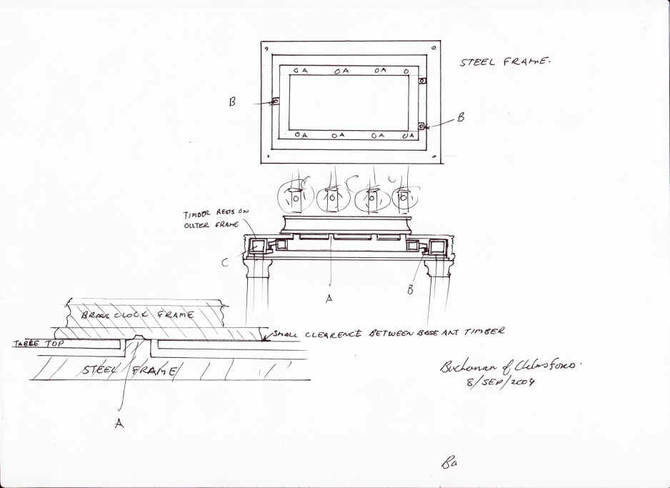
The frame redesign brought up a new problem, however. Under the prior plate-and-spacer configuration we had the main wheel works which included the main weight barrels confined between two 1/2" (1.2 cm) thick brass plates. While these plates were to be extensively fretted in keeping with our curvilinear skeleton design philosophy these plates would, by their nature, provide a ridged structure for the wheels within to be secured. The mass of the four weights is anticipated to be about 330 LB (150 kg), this is in addition to the 200 LB (136 kg) for the movement itself. This mass, especially that from the main barrels will hang from the long frame rails. While the brass is quite thick, the combination of a long horizontal surface coupled with tall vertical pillars mounted on this surface lends to flexure of this structure. With the taller the pillars, of which the corners will be over 15" (36 cm), the error will be more pronounced as the pillars tend to twist inward as the base is pulled downward from the weights. In addition those weights will become a live load under the stresses of winding; adding to this problem. The maximum deflection would be at the upper ends of the pillars, exactly where the trains are their most delicate and exacting. The drawing below is B's answer to this problem. A space frame composed of structural steel will be embedded into the wood stand and remain invisible to the viewer. It will provide the necessary support for the movement superstructure. Notice that the steel is carried through the wood stand pillars, straight to the ground; the same sound structural engineering principals employed in commercial building designs.
Next B begins the custom manufacture of the fly cutters that will be used to make the frame moldings. These are first employed in wood and matched to the metal frame structure to compare styles.
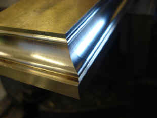
The transition zone between the upper and lower corner pillars is refined in the photos below.
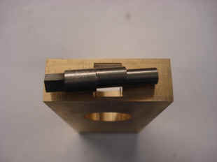
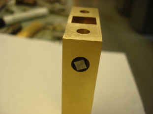
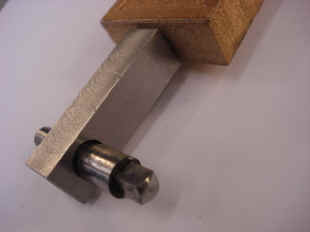
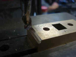
Now begins the fabrication of the pillars and the associated parts involved with securing them to the main frames. B had indicated that he needed a way to rapidly disassemble and reassemble the frame pieces. These parts would need to be cycled scores of times in the course of the fabrication process. Anything that eases this process helps the fabricator. He came up with a square keyed cam as illustrated below. This will also be useful in shipping and servicing. A nice blued screw would have been more in keeping with the general character, but this part due to its function must be very tight. A simple slot head would nor provide the torque necessary and damage to the slot would surely result. A key supplies the safe torque needed. See video clip below for how a square hole is machined.
Next B. begins the fly cutting of the corner moldings. Last photo in set above shows one of the mills used for this process. B. does most of the flat stock which consists of all of the wheel work spokes, pendulum balances and flat stock decorative design work by hand on a scroll saw. This comprises the larger share of the brass stock used on the movement. However, for complex shaping he does have use of various computer assisted machines. The lower rail base molding is pretty straight forward as only one custom fly cutter is needed.
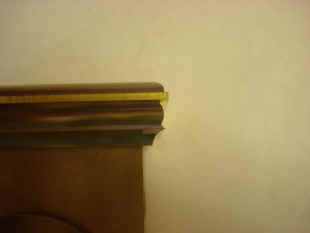
The first photo shows a completed corner of the lower base rail molding. Next photo is how B. makes a female fly cutter from the original male which was used to cut the lower rail base molding. First the raw cutter steel must be annealed to soften it, then the original cutter is used to cut the new tool. The tool is then re-hardened. This cutter is now an exact negative of the original. The new cutter is needed to cut stock for the inside corner mates shown in the last photo.
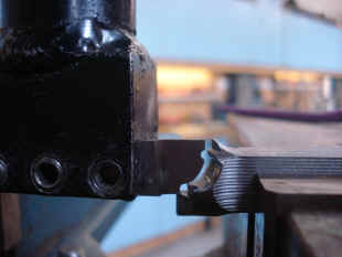
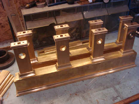
A more complex shape is involved in the decorative moldings that form the base and capitol of the eight lower pillars. Five separate operations involving different fly cutters or other machine tooling is needed to cut the complex profile.
The finished base rails, moldings, pillars, capitols and bases.
The first video shows the movement progress as of the middle of this month. After the first minute, the movement will be turned around so one can see the rear. The second video shows a few cycles of the Robin remontoire. Focus on the small weight and pulley in lower middle area between the two center winding barrels. When the remontoire cycles the weight is drawn up and the fly fan just a bit above and to the left of the weight is activated. The fly does not operate on the same cycle as the two Wagner time flies located at the top. Those operate every 30 seconds and alternate with each other so one is moving each 15 seconds. I wanted the Robin remontoire fly to be activated once per minute and to slightly vary the time at which it will start. A six sided cam performs this function. The Robin fly was purposefully buried inside the mechanism as opposed to the time flies. The combination of the out of sequence initiation along with its position with the movement surprises the viewer and evokes the imagery of a caged bird or butterfly. All the fly fan release timing sequences have yet to be properly synchronized, so they are not perfectly in the their desired cycling events in these videos. Last YouTube video shows the drive wheel for the Robin Remontoire being 'pumped' by the Wagner time remontoire. Also shown is the recoil pawl which keeps the drive wheel in place as the pump arm is being retracted. As can be seen from the clip, more adjustment is necessary on this part. The media player has two short clips of machining functions.
Astro_09-09_vid.mpg Astro_09-09_vid2.mpg http://www.youtube.com/watch?v=R6mDLDTOmBs http://www.youtube.com/watch?v=7BqHXd9FS-o http://www.youtube.com/watch?v=uzTJCI_P7EY
|