Equation of time assembly, begin Robin remontoire, fly fan decoration - May 2009
The fabrication of the equation of time differential assembly. What is the 'equation of time'? It is the difference between the mean solar time, which is our common clock time and the position of the sun in the sky. At noon when the sun is directly overhead it rarely reads twelve noon on the clock. In fact only four days a year will both observations agree. Those are April 15, (tax day!), June 13, September 1, December 25, (Christmas). My guess is the first and fourth dates are coincidental. The rest of the time the sun will appear fast, in other words reaching noon overhead before twelve noon on the clock by as much as 16 minutes 33 seconds on November 3, and as slow as 14 minutes 6 seconds on February 12. This phenomenon is the result of both the elliptical orbit of the Earth around the sun as well as the tilt of the earth’s axis. The combination of these two movements results in the apparent erratic motion of the sun. Both of these factors are shown on the graph and their mathematical combination is the black line. That graphical curve of the equation of time is what is physically represented by the contour of the equation kidney cam.
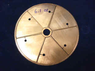
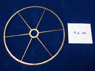
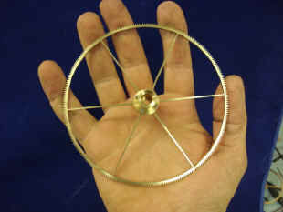
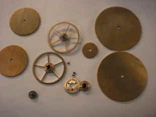
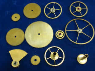
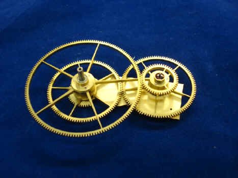
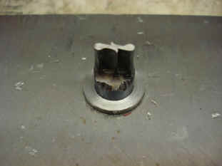
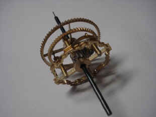
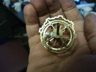
The kidney cam will be made at a later point. The part of the equation of time assembly that we will be dealing with here is how the readout of the kidney cam will be determined. There are several ways this complication can be generated and displayed. The most common and more mechanically simple, being a pivoted hand one end of which rides along the equation of time kidney resulting in a back and forth motion of that hand. This lends itself to a sector dial with a total of 32 one minute increments; zero being in the center with -1 to -16 to the left and 1 to 16 minute marks to the right of the center zero position. We take a different, more complicated and I believe more elegant approach based on Breguet's design. Here a differential is installed between the readout hand and the kidney cam. In this way the hand will rotate at the same speed as the mean solar time minute hand. Mean solar time being what we are all familiar with as regular clock time. With this hand mounted in the same pivot position in the center of the clock dial as the regular minute hand, the equation hand will at any time cycle between fifteen minutes behind or ahead of the regular minute hand throughout the year. The difference between the two times being read right off the same clock dial instead of a separate sector dial. The equation hand is usually distinguished from the regular minute hand by a sun symbol mounted near its tip. B. begins with the main drive for the equation assembly. Note the weight measurements in the first two photos. The wheel blank is 6.1 oz. The final wheel comes in total 0.6 oz. This calls back to our original set of raw materials coming in at over 3/4 ton for the movement, with the finished item expected to be under 300 lb. The delicacy of the wheel is better revealed in the fabricator's hand.
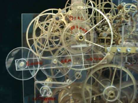
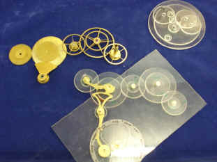
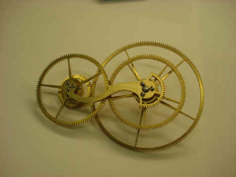
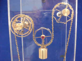
At this time B. made a mockup in plastic to demonstrate proof of concept as well as the overall look. The mockup process is one that has been repeated in wood and plastic throughout this project. Below is B's first design. It looked too much like the Wagner remontoire which would be located nearby. This is shown in the second photo where the swing arm of the differential is a similar one to that of the dual remontoire located behind. Of course the remontoire cycle every 30 seconds while the equation's cycle in one year. B's initial concept differed widely from that which was in the original wood movement mockup which I had liked better. So this design was rejected. Again not surprising that we encounter these setbacks in a project of such novel design and complexity.
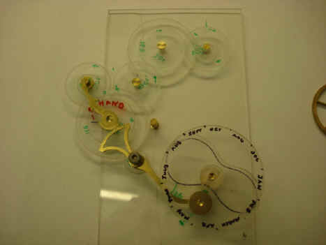
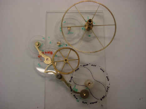
The next day a new mockup was created more in keeping with the original design. This eliminates the central swing arm and replaces it with a 'tail' as shown to the far left of the first photo. This is driven by the toothed sector gear. The second shot has a few completed wheels inserted. The videos below show the movement of this system
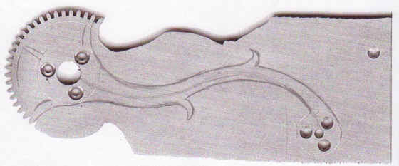
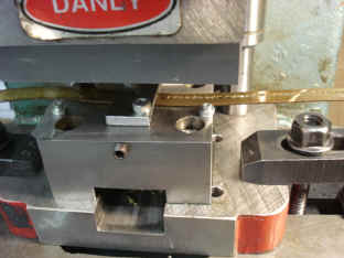
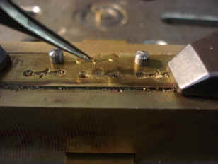
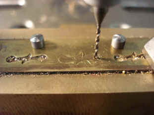
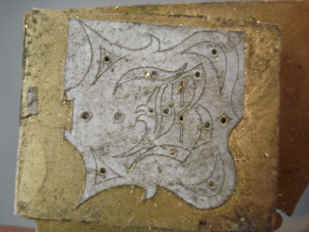
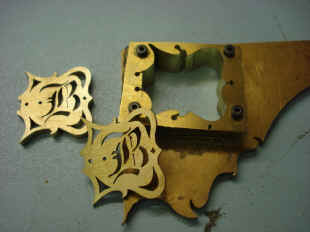
Now the fabrication of the various components begins in earnest. Last photo shows B's freehand drawing on the brass blank of the differential 'tail'. Once again a consistency of design elements is kept with our organic curvilinear flow punctuated with vine spars. The last photo shows the completed tail. Notice this is a rare area where one will not see a jeweled chaton or a jeweled pivot. What shows is the end of a steel (stainless) arbor. This is because there are multiple wheels on these arbors so the wheel centers themselves are jeweled on one paired set, with the other using small ball races since here there are three concentric moving wheels making the use of jewels impractical.
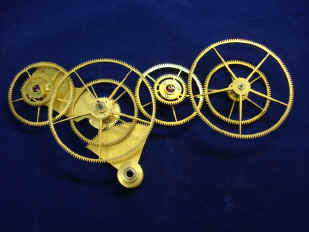
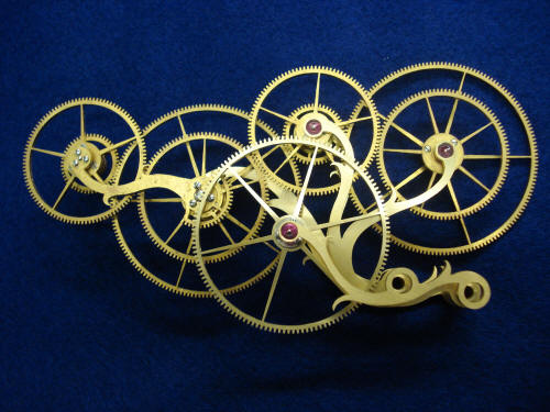
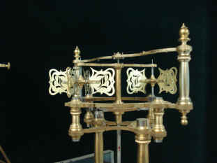
The completed differential assemblies. Note, these photos were taken in July 2010 and were placed here to give the reader an idea of how the completed assembly will look. The left photo shows the lowest maximum position of the differential, sun slower than mean time and the right photo the highest maximum, sun faster than mean time.
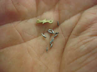
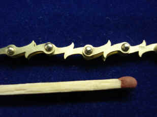
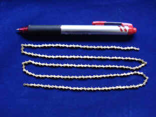
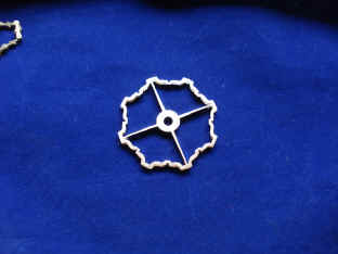
Now B. begins the Robin remontoire. This system will be used to trip the celestial train once per minute as driven off the time train. It was a late addition in the development of the clock's design. Originally we had the celestial train tripped each minute through a conventional pinned wheel that would allow the celestial train's main weight to drive that part of the clock. This was to be mediated by a fly fan located deep within the movement to give the impression of a caged butterfly within the movements vast structural complexity. When we changed the design to have the celestial train and time train driven jointly we had a problem with what to do if the celestial train should fail or if I simply wanted to only run the time train (and or the strike trains independently). Don't ask why this should be necessary, but I thought that due to the complexity of the celestial train, if it should fail, I'd still like to have the rest of the clock available to function. We decided to have the two trains driven jointly because there was a vast difference between the weight needed to drive the time train (large) and that needed for the celestial train (much smaller). in this way we could equalize the two weight which would look aesthetically more pleasing. However, since the celestial train was being slaved to the time train the one minute trip was no longer necessary and by extension the caged butterfly. Of course the fact that the celestial train would be driven directly from the time train could introduce error to that train. So we decided to combat both problems by driving the celestial train via a Robin type remontoire. We now are able to keep the fly and add a another fancy remontoire! And as one will see it is fancy indeed. First comes the manufacture of the remontoire chain. We wanted to carry through our curvilinear / spar design right through to the individual chain links. The photos below show the manufacture of this chain which will contain about 400 pieces for a 30" length. First a die and punch are made and the links are then punched out from flat brass strip. The end holes are drilled and each link pin in made. Notice how small these are compared to the hand holding them. The links are then assembled and the link ends are flattened to conform with the link's face. A portion of chain is shown with a pen for scale. Last photo shows one of the drive sprockets for the chain. Since we have a chain with unusually shaped links this requires a very interesting looking sprocket!
Next begins the remontoire safety clutch. This is what's needed to allow the time train to continue to run in the event the celestial train should jam. Remember that the time train will be using both its own as well as part of the celestial train's weight and the balance of those weights is used to reload the Robin remontoire. With a conventional remontoire system, should the celestial train fail to move, the remontoire will not properly cycle and will jam up when reloaded a second time without the chain being advanced to drive the celestial train. The last photo shows the remontoire weight of just under 2 ounces that will drive the celestial train which will contain over 100 wheels! This is possible because the weight is being applied near the top end of the train and all of the elements of the celestial train move very slowly. Last photo has the initial component mockup positioning. The balance of the remontoire will be completed next month.
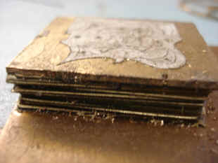
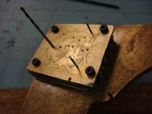
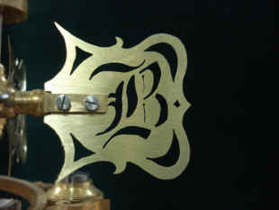
Now we proceed to the final fly fan blade design and decoration. Each individual blade is made from a thin brass material precluding the use of the jewelers saw to cut the profile and decoration. B. gets around this by sandwiching the blades and then cutting 20 of them simultaneously from a template affixed to the stack shown on the first photo. This also ensures that all the blades are exactly uniform.
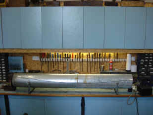
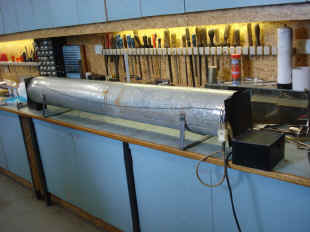
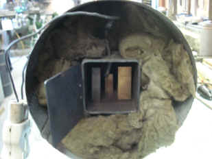
Below is a special-built furnace B will use to heat the longer brass stock that will later be used in the lower frame members of the movement. This process stress-relives the metal. This will prevent the long pieces from curling like a banana under the process of fly cutting.
Below are two videos showing the equation of time mockup and how the differential works to keep the equation minute hand turning in step with the mean solar time minute hand with the compensating time differences between the two. Astro_05-09_vid.mpg Astro_05-09_vid2.mpg
|