Complete lower movement main frame; hammer lift cam wheels - October 2009
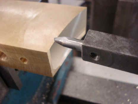
B continues fabrication of the movement
frame base. First step is the curvature of the main frame base rails. Since this is a
fairly gentle curve, it requires a cutter mounted on a long arm to give a large diameter
swing. First two photos show the rail end shaped. The rest the shaping of the rail sides.
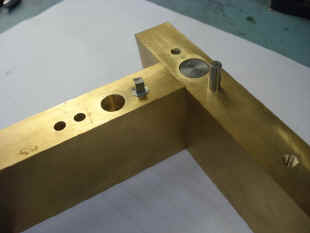
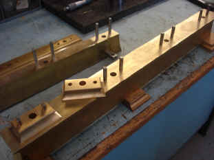
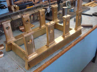
Below is depicted a novel way (at least as
applied to horology) of securing the various pieces of the frame together. (first
five photos). It’s also not unfamiliar to anyone who has had purchased
furniture from the large retailers like IKEA where it comes unassembled and the buyer has
to do this. Basically two parts are held together through the use of an anchor part, the
tongue, which has a hole. The mating part has a matching hole that has a slot into which
the tongue anchor piece hole fits. Into these two parts each with their holes matched up,
is inserted a shaped pin. This is basically a cam that when turned, will cause the tongue
with its hole centered between the slotted hole part to shift slightly drawing the two
parts securely together. This design allows one to hide what otherwise would be at least
two screws to secure the frame corners; leaving the method of fastening completely hidden.
It also allows for quick assemble-disassemble cycles, which makes the fabricator's job
easier. The cam is turned by a key inserted onto the squared arbor. Similar to design used
to secure pillars to base – see September. Notice the holes above and below the
tongue, second photo. These will have guide pins that will further strengthen the joint
(similar to the one positioned nearby on the horizontal rail surface). These pins are not
just slid into blind holes but are screwed into a threaded hole at their base.
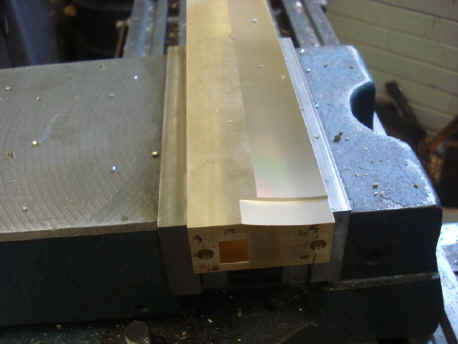
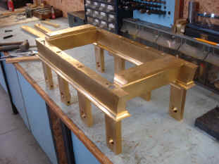
Next three photos show the attachment of the lower base moldings.
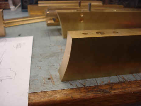
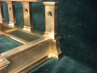
Below are photos of some frame molding
details. This rich detail is the result of many separate machining steps and proliferation
of parts. The inside corners are particularly difficult to make (see last month’s
installment). The third photo shows what to me, is an outstanding example of B’s
quality of work. Even the inside base rim has a molding; something I would never had
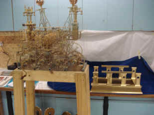
expected. Next photo shows the frame near the movement to date. This is deceptive as
the frame is further back and thus looks smaller compared to the movement than it should.
Yes the parts do fit as depicted in the next two photos. One can see already how this
frame design allows for more of the wheel works to be seen than would otherwise be
possible in the former design employing a conventional plate and spacer design - even with
those plates skeletonized. Total frame weight approximately 77 lbs. or 35 kg. 126 parts so
far.
B sent some fancy finish photos of the
frame. He began the frame on the 7th of last month and has accomplished such a
beautiful object in just over a month. He will now break from any further fabrication of
the frame since he wants to make as many parts that will be between the plates as possible
so as to better know exactly how all of these will be planted before finalizing all of the
frame. This makes sense, although I think the frame design is pretty well already set!
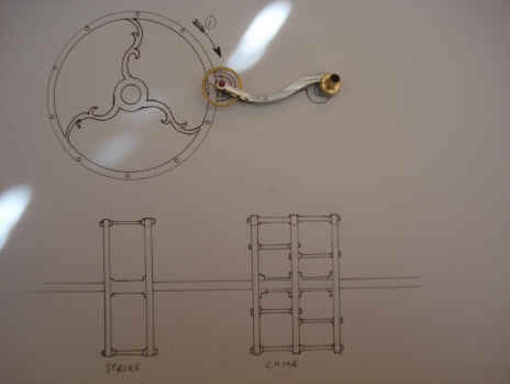
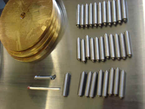
B sent a drawing of his concept for the strike wheels that will contain the lifting levers for the bell hammers. The fabrication of the strike cam assemblies now begins. Total of thirty pins in two different sizes. Notice that each is smaller than a match stick, second photo. The style of the wheels is in keeping with that of the balance arbor end plates.
Below is a playful photo showing the swarf
that is generated from the making of the screws for the quarter and hour strike hammer
lifting cam wheels. Shown is the basic rod stock from which the 100 screws needed for
these two assemblies were made.
Total parts excluding the arbor and collets
are 135. A conventional design would contain at most 15 to 20 parts with most containing
less than five when using a solid cam for the hammer lifters.
Below the hammer lifting cams are installed
into the movement; hour strike cam in background and quarter in foreground. The end view
shows that even the side that has ‘less components’ compared to the opposite
side that contains the time train remontoire, we are seeing this area filling in quite
nicely. 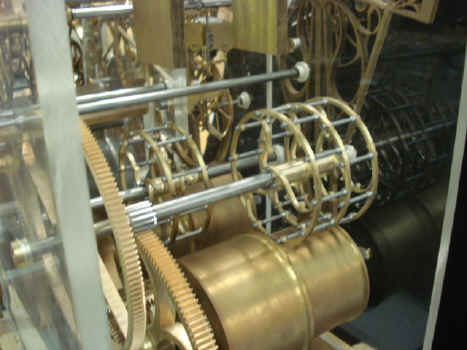 
Astro_10-09_vid.mpg Astro_10-09_vid2.mpg Astro_10-09_vid3.mpg
|