|
Time train, pendulum support, time, celestial, equation train frames fabricated - July 2010. The halfway point
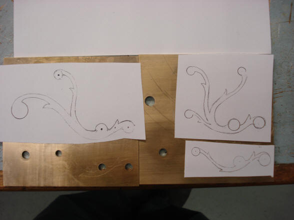
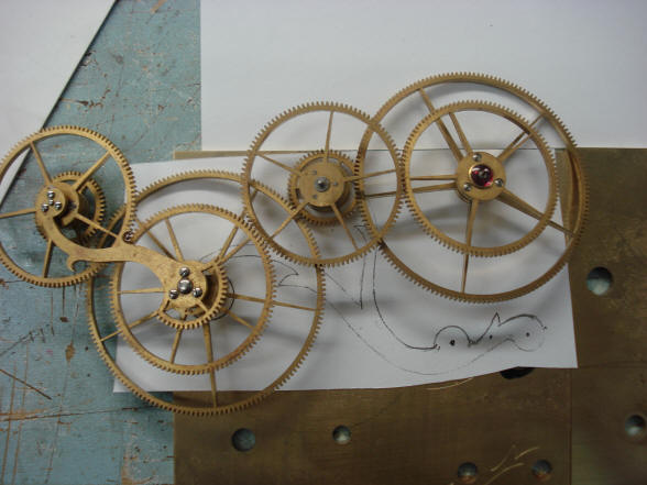
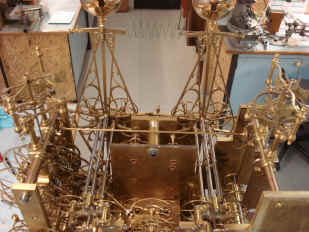
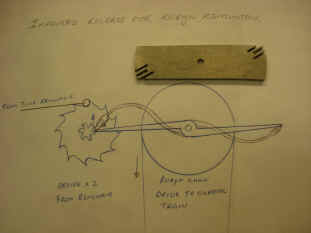
This month marks a milestone. I believe we are now at the halfway point in the creation of my fantasy horological machine. Metal was first cut in August of 2007 so this month makes the third year. The project began with my conceptual drawings in October of 2003 and continued refinement though the first half of 2005. Since then steady progress has been made towards completion. It's been three years since metal began to be cut, and if momentum is kept and considering our path along the learning curve of this project, we should be finished in another two and one half years making this nearly a decade long endeavor. Now for this month's presentation which I believe will bring much satisfaction to the reader. Before beginning the upper frame assemblies, Buchanan revisits the equation of time assembly to create the frames needed. First hand-drawn designs are created and the final shapes are scribed onto the brass blanks. Next photo shows the wheel works which had previously been made in May of 2009 arranged as they will be in the frames. The bottom frame is shown. Note that one sub-frame was made at that time, the one connecting left most two wheels.
Next one of the upper sub-frame drawings is checked for fit. The second photo shows the frames complete and the equation assembly unit placed on the clock frame to check for proper position.
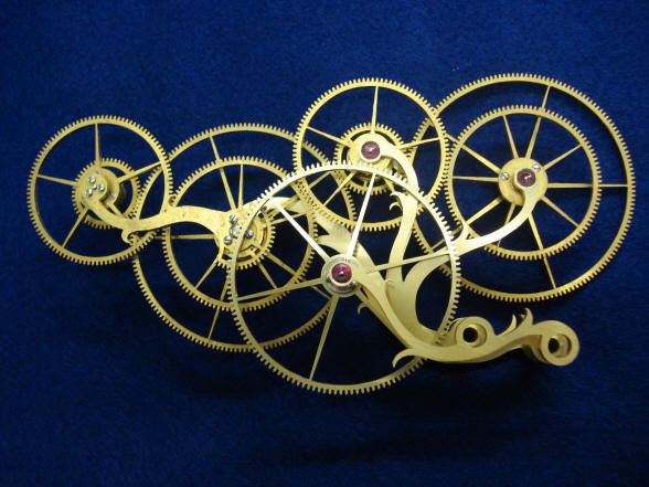
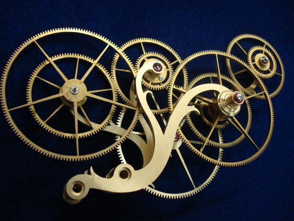
The equation wheel works give a particularly nice presentation.
We spent the rest of the month on the final design and fabrication of 2/3rd of the upper frame assemblies; the time train and the central sub plate units. During this period other smaller parts are being re-machined to enhance visual appearance or to contribute to mechanical efficiency.
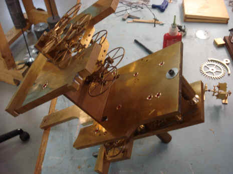
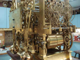
The pillar design adopted in March of 2008 allows the movement to be disassembled into separable units; greatly enhancing the ease of construction and serviceability. On the fabricator's bench, above, are the central sub plates, left, containing the escapement, anti-friction wheel assembly, orrery support structure and the Robin remontoire which will mediate the release of the celestial train. The time train assembly, right, also encompasses the differentially driven dual Wagner remontoire which will drive the two grasshopper escapement wheels (front plate removed). Note the tray of 120 jewel pivots on the bench in the upper background.
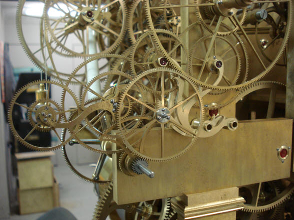
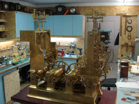
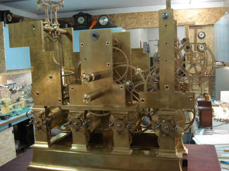
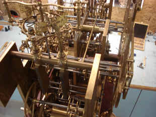
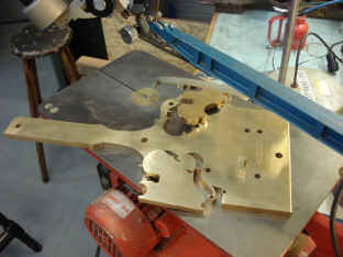
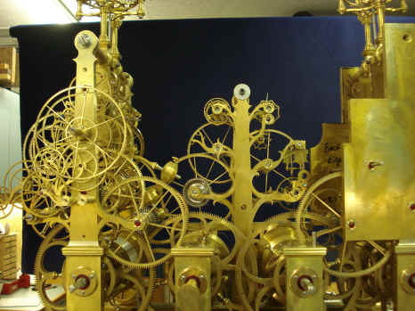
The rough time and strike train plates are mounted to the lower main frame. Next the central frame is inserted, both rear views.
Further views of the built up rough upper movement plates.
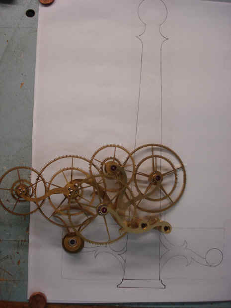
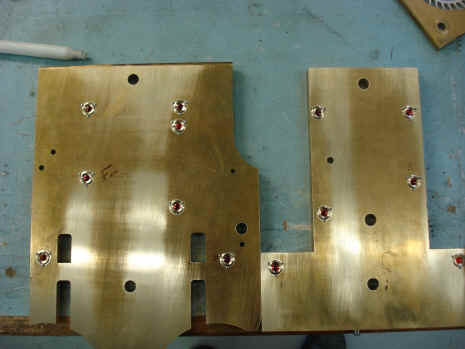
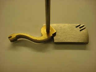
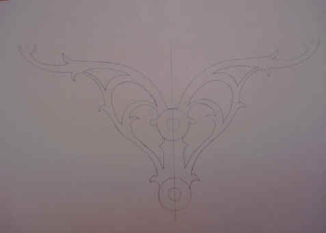
Now begins the decorative design of the time and central frames. Drawings are made up and presented to me for approval. Some minor changes are suggested and these drawings are then used to compare and align parts that have been fabricated to check for fit and visual presentation. The first photo shows the equation of time differential drive assembly set on top of the time train pillar drawing. The second shows various components of the Robin remontoire celestial drive which are still mounted to the original plastic frame member and set on top of the drawing of the proposed center frame design.
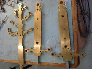
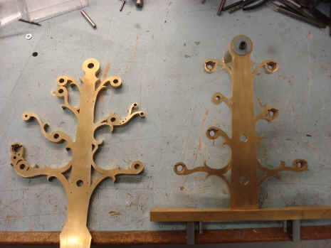
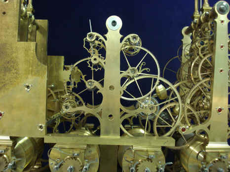
The first two photos show the cutting out of these rough frame pieces into their final shapes. The first is one of two plates for the center assembly, the second is of the one of the two time train pillars. The third shows the rear center frame in its 'tree' form and the two time train pillars.
Above are the before and after photos of the front and rear center 'tree' plates.
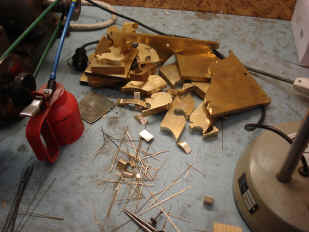
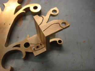
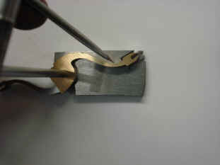
The first picture shows scrap from the cutting of the central and time train frames. notice all of the long thin cutting blades scattered just below the scrap pile. These are the number of blades worn and broken from the cutting of just these four plates. Next we see the hand-cutting of a complex three dimensional part. All of the flat stock is cut this way by the fabricator and the entire movement will reflect the very tiny imperfections and unique features that can only be associated with hand made work. The next four photos show some of the parts that will fill in the center tree plates. Shown are the overrun clutch, levers and fly control fan all in connection with the Robin remontoire.
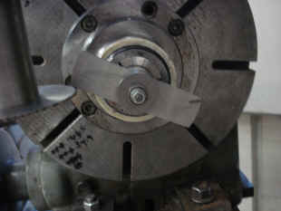
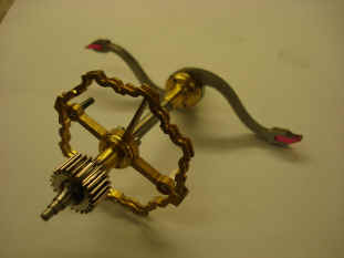
The Robin detent is now re-made from a straight legged to a curvilinear
legged design as specified in September of 2009. First photo shows the initial steel blank
being slotted on a lathe. The second the completed slotting as well as one of the over 100
ad hoc drawings that are made as the project proceeds along. Next, in order to be sure that both arms are identical, a
template is first made from softer brass, an easier material to shape, and the design is
scribed into the harder steel, turned 1800 and scribed again prior to cutting
this blank to its final form.
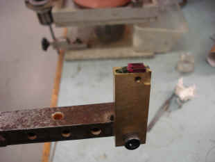
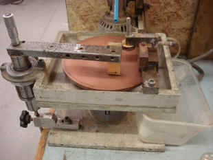
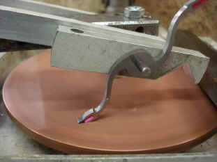
The jewels are now polished on the machine's copper disc charged with diamond polishing compound. Lastly, the new detent is mounted to the Robin chain pulley. The jewels are secured with shellac. These will later be removed so the steel detent can be heated to obtain the desired blue color and reattached.
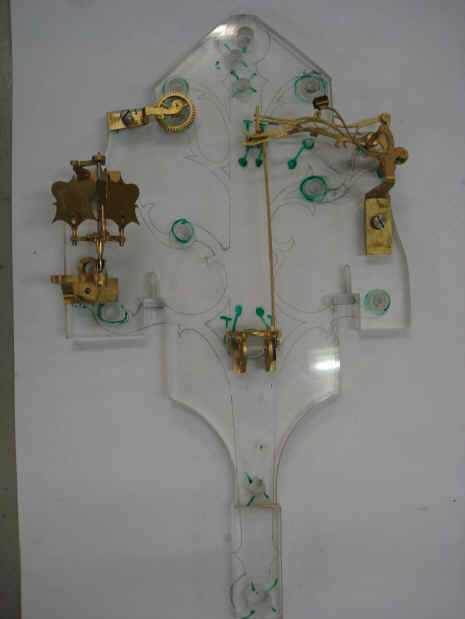
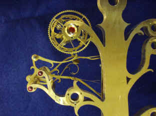
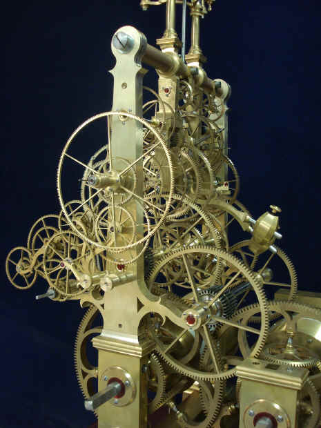
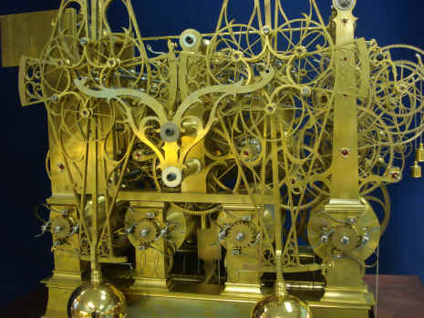
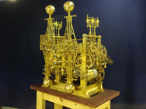
The fabricated frames are now fitted back onto the lower movement superstructure. I have to comment that the effect is stunning. Look at the way the wheels in the time train literally spill out from the frame allowing for maximum visual impact. The architectural features of the pillars where the upper and lower frames meet adds a classic design touch in keeping with the entire lower frame's motif. This lower 'classical structure' provides the foundation for, and morphs into, the organic forest of wheels held by the curvilinear trees above. The second pillar in the first photo shows a square slot where the upper and lower frames have a hidden 'quick connect' feature that allows these two parts to be seamlessly joined (see September 2009 installment for details).
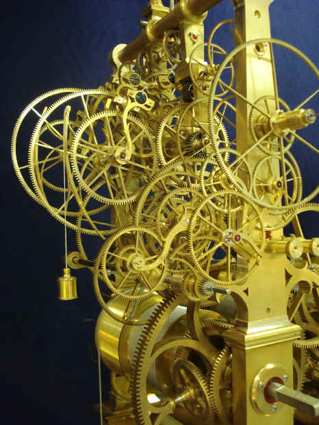
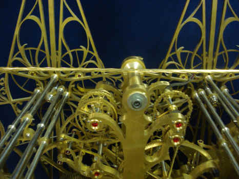
Next are views of the central frame trees. Again the design allows for maximum viewing of the movement works. The tree branches will later be progressively thinned as they move toward the top of the tree just as they would be in a live plant. The round ends that contain the chatons will remain at 1/2" since the arbor lengths are all fabricated. However, this will be a bonus as these areas with their big red cap jewels will be the ripe 'fruit' at the end of each branch. There is still another embellishment to be done to all of the upper frames. The central trunks will be spark-eroded to develop a recessed matte finish in their centers, a nod to tree bark, and this area will be surrounded by a polished border about 1/8" wide. The inside face of the trunks will remain fully polished to produce multiple reflections of the wheels between them.
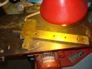
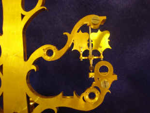
Next a drawing is prepared for the design of the plate that will serve to support the rear pendulum pivot points. All parts are cut in one pass...looks easy; like cutting butter! But this is 1/2" thick brass plate!
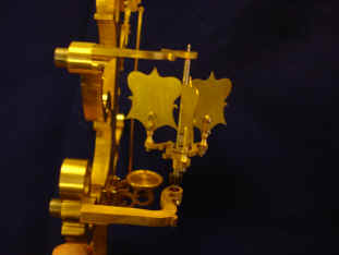
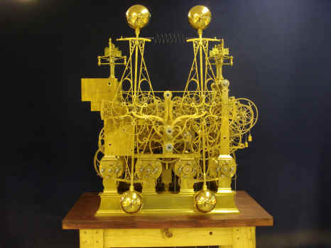
With the rear pendulum mounting plate complete, the pendulums are now back in place. Most clock movements can be pretty dull looking from the rear, but not this one! The last upper frame to be developed is that which will contain the quarter strike train. And what forest would be complete without animals? On the second video below notice how B has fashioned the two escapements and their pallets into making each a pair of fanciful birds complete with jeweled beaks, head with comb and a flourish of brass and steel tail feathers. Below is a 23 minute video montage of the project from its design inception in late 2003, through the creation of the first design mockups and full scale model in July 2006 and fabrication from July 2007 through the midpoint of this project as of this month, July 2010.
Astro_07-10_vid1 Astro_07-10_vid2
|