Rough upper frames complete, some finish & trim work - June 2010
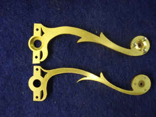
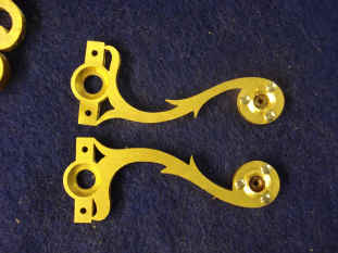
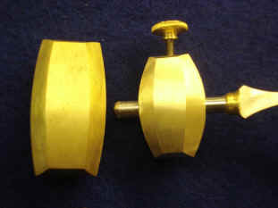
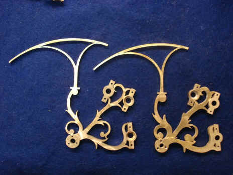
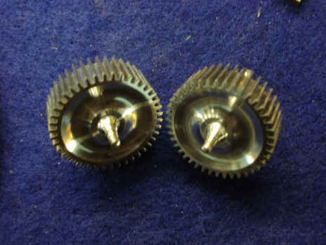
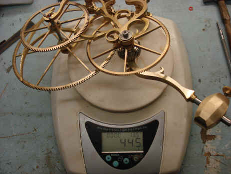
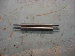
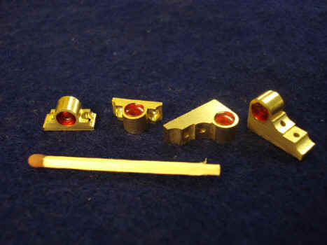
This month we continue the process of fine-machining some of the existing parts. In some cases we do this to add embellishments, while in others it's done for aesthetic reasons. Below, however, we are attempting to also shave off mass in addition to bringing out some finer fret work in the metal. These parts are from the dual Wagner remontoire swinging frame cages. Once the clock was up and running for a while we noticed that the escapement would occasionally trip, that is a tooth would be skipped by the grasshopper pallet. Grasshopper escapements, if not properly designed, are prone to this. We were very careful in this design and even had the help of an expert in this field, Mr. Peter Hastings back in December of 2008. What we noticed was a two-fold problem. One was the fact that the escapement wheels were being a bit over-powered; the remontoire was too massive for the delicate escapement and the other was a bounce of the cages as they reached their apex. Recoil is an inherent characteristic of a Harrison grasshopper escapement. To the best of my knowledge there has never been this type of gravity driven remontoire attached to such an escapement. Harrison had, in fact used a spring driven remontoire, also his invention, in his second marine chronometer, H2, but the action of this remontoire as opposed to Harrison's is completely different. In short, when our remontoire would reach the apex of it's travel, if the escapement pallet is at the very edge of the tooth during recoil, the mass of the remontoire cage can create feedback through to the escape wheel and cause the pallet to trip as well as the cage to have a disconcerting bounce. These problems did not make themselves known during the test phases of this system in the working plastic mockup back in April of 2006. My guess is that because everything was made of plastic the weight problem was not there. A second attack on this problem was the development of a 'soft stop' star cam. In a conventional Wagner type remontoire there is a star cam that comes into contact with a detent that halts the reloading of the swinging cage when it reaches its apex, see demonstration. The star cam is fixed rigidly fixed to its arbor resulting is a positive and sudden stop to the cage when the cam comes into contact with the detent. In our design the star cam is slightly spring-loaded. This allows a bit of travel to the cage after the cam comes into contact with the detent; preventing the mass of the cage to interact with the Harrison recoil preventing tripping and the annoying cage bounce. Below are before and after photos of some of the parts that were re-machined. Pinions were also dished for weight and aesthetic considerations. Some screws have been blued to give an idea of this color contribution, but have not been fully polished yet. The last photo shows the re-machined half-section of the dual remontoire in at 445 grams. This was originally 676 grams, a reduction in weight of 34.2%.
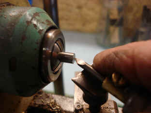
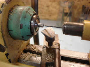
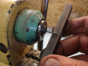
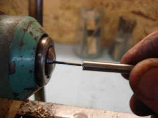
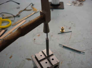
Since this process has not been shown before, below are the steps B takes to insert tool steel pivots into each stainless steel arbor end. I wanted to have all of the arbors made of stainless steel so as to avoid any concerns with rust. However, the stainless steel we could find in the sizes we needed were not of the grade that would harden to the degree one gets with tool steel. It's estimated that 250 or so wheels will have conventional pivots, so this operation will need to be performed 500 times. The balance of the wheels will be in roller bearings. Those wheels are ones that experience a significant amount of torque like the weight barrels as well as the next wheel up each train as well as any wheel that will turn faster than once per hour. The rest will run in dry jeweled bearings. We are confident that these dry bearings will perform well given that the arbors turn slowly with minimal torque. The Harrison escapement is also famously known to operate without the need for oil. Eliminating oil from as much of the mechanism as possible will greatly enhance the time between major overhaul. The main reason for clock failure is the gumming, drying and contamination of oil. Breguet is quoted as saying, "Show me the perfect oil and I will give you the perfect watch", exemplifying his same concerns. The pillar frame design also allows for greater ease of serviceability compared with a conventional plate and spacer design. In future installments, one will be able to see this more clearly as the frame is more fully developed. Because this machine is complex the odds are there will be the need for service more often than one would experience with a conventional mechanism. I wanted to make this as easy as possible so it will remain operational. All too often in the past when a clock, even a significant one, breaks down and is beyond the means for most people to repair, it falls into disuse and even destruction. (Full disclosure, for the sake of visual impact the fly fans run in oiled jeweled pivots, but these systems are located in easily serviceable areas). One might ask why not put all arbors into roller bearings? The reason is that jewels look beautiful and the main thrust of this endeavor is to create the maximal visual impression and pleasure. A gear-head's delight!
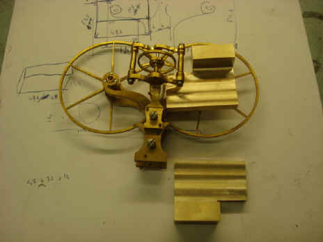
Next is an example of the many, many changes and (hopefully!) improvements that take place during the fabrication process. In the first photo note the drawing sheet beneath the part. These are sketches of how the next component will be integrated into this assembly. This being one of four pair of antifriction wheels that support the dual counter-rotating escape wheels. The center wheel in juxtaposition at 90 degrees is a thrust bearing to keep the escape drive bevel wheels in line. All bevels by the nature of their geometry create a side thrust 90 degrees to their plane of operation so such a device is needed if there is no other restraining mechanism like the shoulder of an arbor against a plate. Since the escape wheels literally 'float' on the antifriction wheel assembly no other such control is available. The second photo shows the close up of the block of brass seen in the prior photo and how one might add the bearing needed for the diagonal arbor that will drive the escape wheels. The easy and cheapest way out here would be to simply fabricate a separate cock to hold this piece and attach it onto the existing assembly.
That's not how we work here! A redesign of the exiting top bridge to the thrust bearing will be made. One might ask if this is expensive and wasteful, well yes to some degree. But since no overall design-to-build plans were created prior to construction this type of re-work is inevitable. Considering the many design changes we made during this project such a set of plans would have been of limited use in any case. The need to junk prior work, all things considered, has been remarkably small. The first photo shows how we plan to extend the current bridge to incorporate the new bearing block (this block is in rough form and will later be refined). The next photo shows a full sheet of brass stock that now incorporates both the thrust bearing bridge (its jewel is hidden by drive bevel arbor) and the support for the diagonal escape wheel drive bearing block. This will later be skeletonized in a similar fashion as was the original thrust bearing's upper, jeweled bridge.
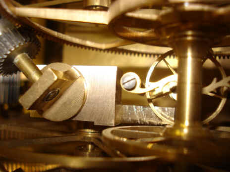
Remember in the photo above the ugly diagonal bevel drive bearing? These are the finished product below. Notice they have red, plastic 'jewel' end caps. These caps hide from the front view the fact that there are tiny roller bearings used in these parts. The bearing to the far left shows the rear side, which has a red plastic ring to hide the inner surface of the roller bearing. In no way will anyone be able to see evidence of roller bearings front to back anywhere in the mechanism. Next is a view of the undercarriage showing a specialized bolt which will secure the lower end of the center sub plates to the main frame base. There were two issues here requiring a special bolt. First there was very little clearance between the head of the bolt and the opposite end of the frame precluding the use of a conventional screwdriver and thus a standard slotted screw head. To get around this B drills two hole at 90 degrees to each other. In this way a sturdy pin can be inserted to properly torque it down; known as a Tommy pin. Of course one could have also used a modern hex-head bolt design for this but we did not want to use this design in this project. Also a hex-head requires a wrench which risks coming into contact with and scratching the surrounding plate. The second issue is the need for this plate to be positioned straight down. Therefore, a locating shoulder on the round cylinder cannot be used. So the bolt itself has a slightly tapered shoulder that will properly align the plate to the hold as the bolt is tightened up. The ugly cylinder will later be decoratively machined.
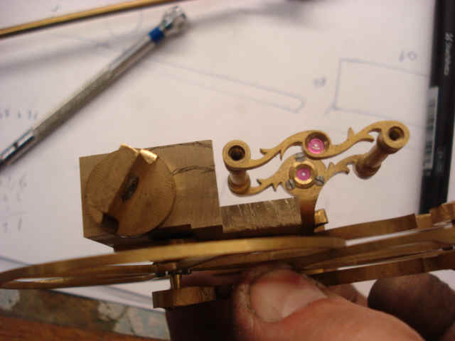
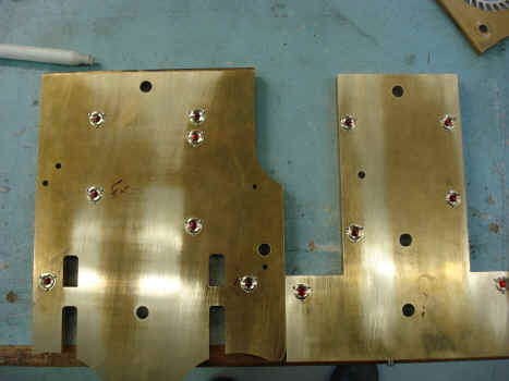
Here the two center sub plates are shown with their thirteen chatons in position. Next the preliminary positioning of a few of the Robin remontoire parts which will mediate the celestial train. To the far right and off the photo is the tail of the plate through which the Tommy bolt is inserted as described in the prior paragraph.
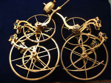
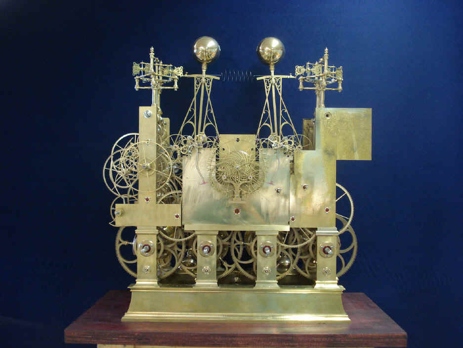
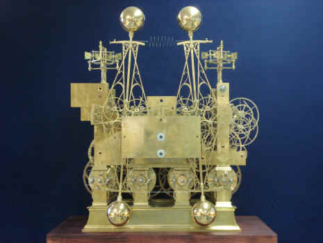
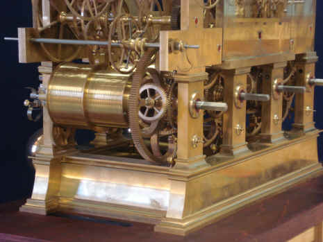
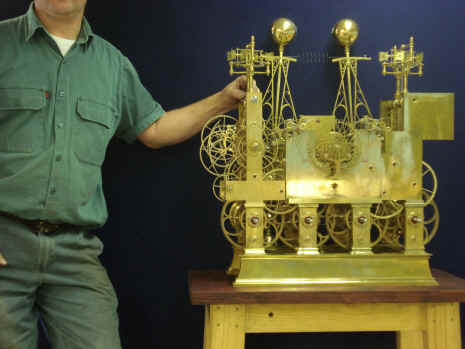
Here are some photos of the movement to date. We have reached a milestone where I believe we have pretty much reached the halfway point on this project (excluding the case and stand). I started this with initial design work in late 2003. The fabricator came on board with his design and mockup construction models beginning in January 2006 and then the actual cutting of metal in July 2007. I expect completion in the next two and one-half to three years making this a decade long effort. Nearly all of the wheels between the main plates are done for a total of about 100 wheels out of an anticipated 300+ plus total. More than a third of the remaining wheels are contained within the grand orrery with the balance connected to the twenty or so complications. Next month begins the skeletonizing of the upper plates. The movement will begin to look dramatically better. The last photo give a better impression of the over all size of the machine. When looking at the individual parts and assemblies it's easy to think that this clock is much larger than it actually is.
|