Demonstration clutch parts, project to date photos; films - August 2010
This month there were simply a variety of 'housekeeping' chores centered around refining and developing the beginnings of various systems. There are a series of good photos and film clips showing the movement to date, near the halfway point. For those who have not followed this project or have just come by it, I have written an on-line synopsis of the project to date. Any comments or suggestions are always welcome. At this point I wanted to bring some perspective to the time that has gone into this project to date by comparing some other major clock projects in the past to this one
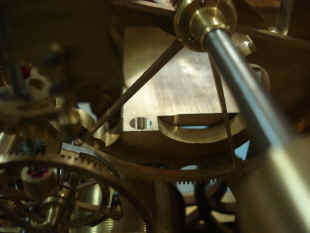
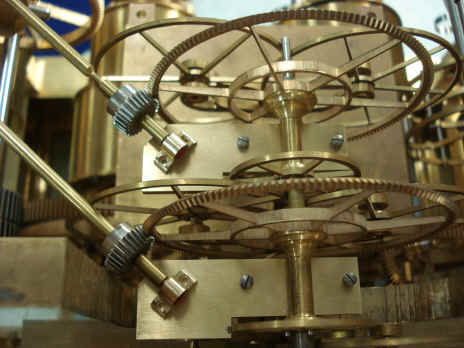
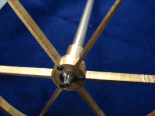
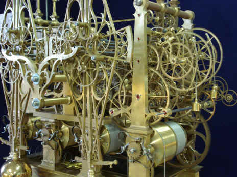
Shown above is the center horizontal section that supports the escapement antifriction wheel assembly. Due to constricting space, a Tommy bolt is used to secure this plate to the vertical pillar/tree. Note how the plate is slightly 'necked' around the area of the tree which would otherwise touch the plate, another nice design touch.
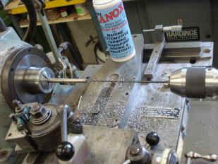
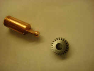
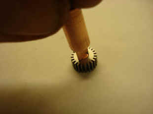
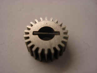
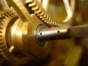
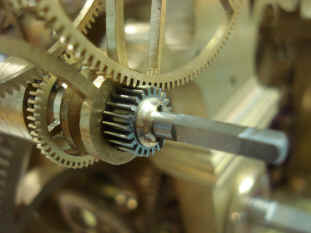
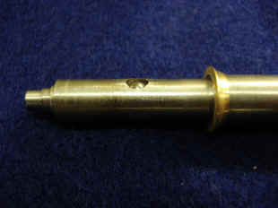
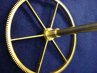
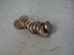
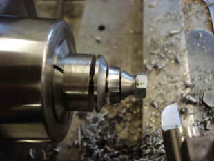
The first photo shows a thirteen inch hole being drilled through a steel rod that is less than twice the diameter of the drill. It looks to be a tricky job. Next a series of photos showing a gear used in one of the celestial train demonstration stations. Here a 12:1 ratio will be used to fast-forward the celestial functions. The copper part is used in an EDM machine to electrically erode the recess needed for the set pin that will secure the gear to the arbor. This pin will reside in the hole closest to the bearing, fifth photo. The last photo shows the finished decorative collar and the second taper pin completing this assembly. The EDM machine is useful when one needs to create a recess that otherwise would be difficult to produce by conventional means. We anticipate using this machine to create the decorative base-relief designs on the upper pillars.
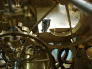
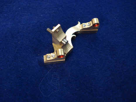
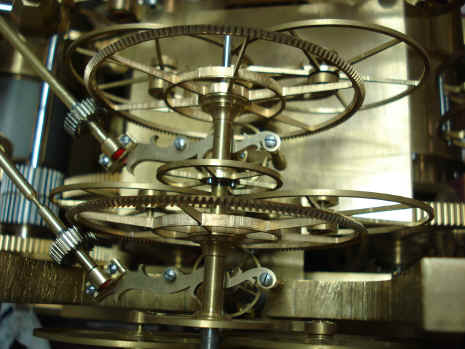
Shown here is the compound cock for the driving (remontoire) end of the dual diagonal escapement drive arbors. Second photo shows this part installed into the movement. The pivots are miniature ball races covered by a red ring to mimic a jewel.
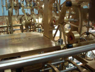
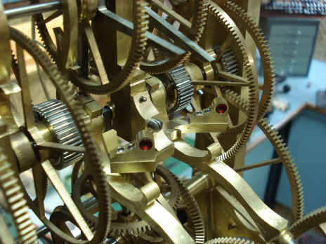
Next is the redesign of the two upper bridges holding the two bevel wheel side-thrust bearings. these were first made in September 2008, first photo. The redesigned initial rough blanks were made last June, next photo. These now have the additional function of holding the bearing blocks for the opposite ends of the diagonal drive arbors to the escapement wheels, next photo. The last photo shows both ends of the diagonal drives. On the left the remontoire drive end, and on the right the escapement bevel wheels drive.
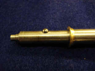
The first four photos are of a
demonstration clutch detent or ‘click stop’ selector mechanism. This will use a
ball bearing within a dual cavity to give the user the positive ‘feel’ for when
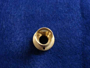
the proper position is clicked into place. The third photo shows the dual lobes into which
the ball will click into, giving indication of fast or slow setting for the orrery
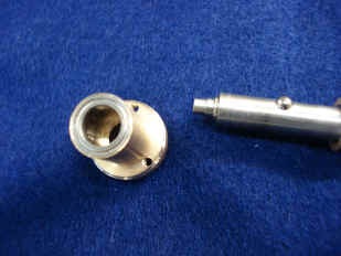
demonstration speeds. The fourth photo shows the ball race mounted. While we are generally
following the principals of the best makers of the 18th century, we still will incorporate
modern design techniques where applicable. The fourth photo shows the ball race in place
on the cavity piece.
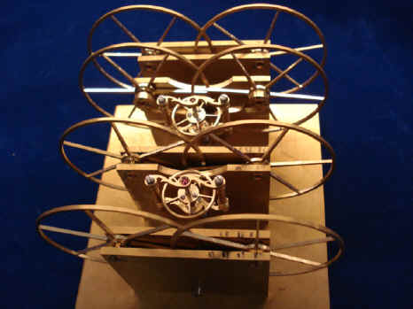
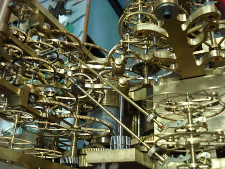
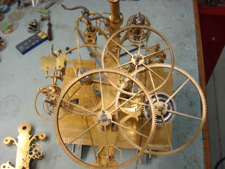
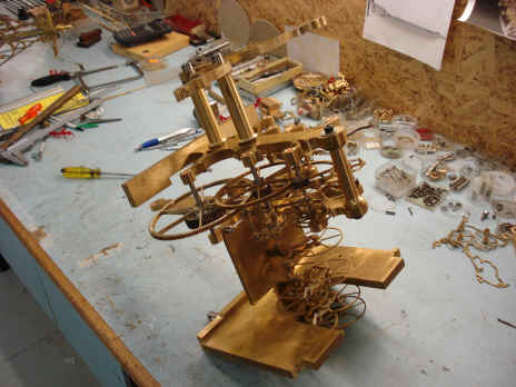
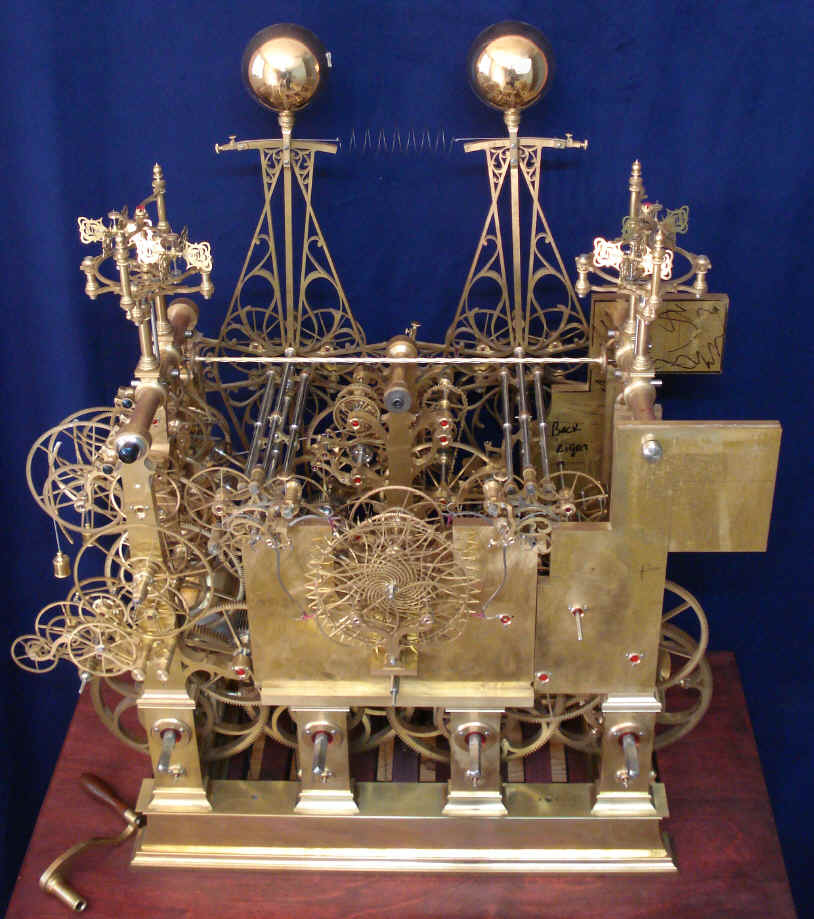
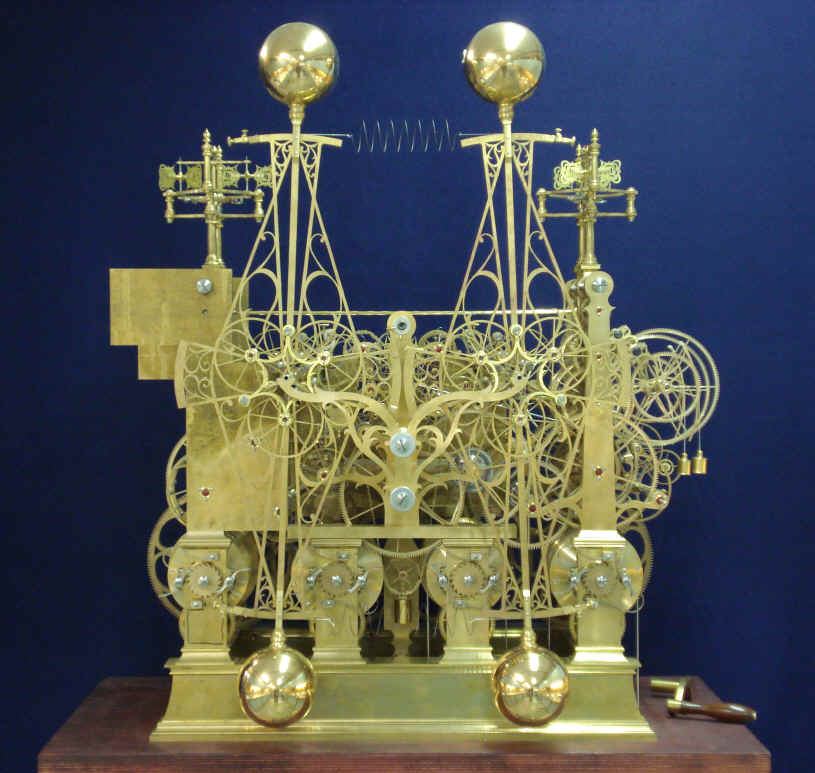
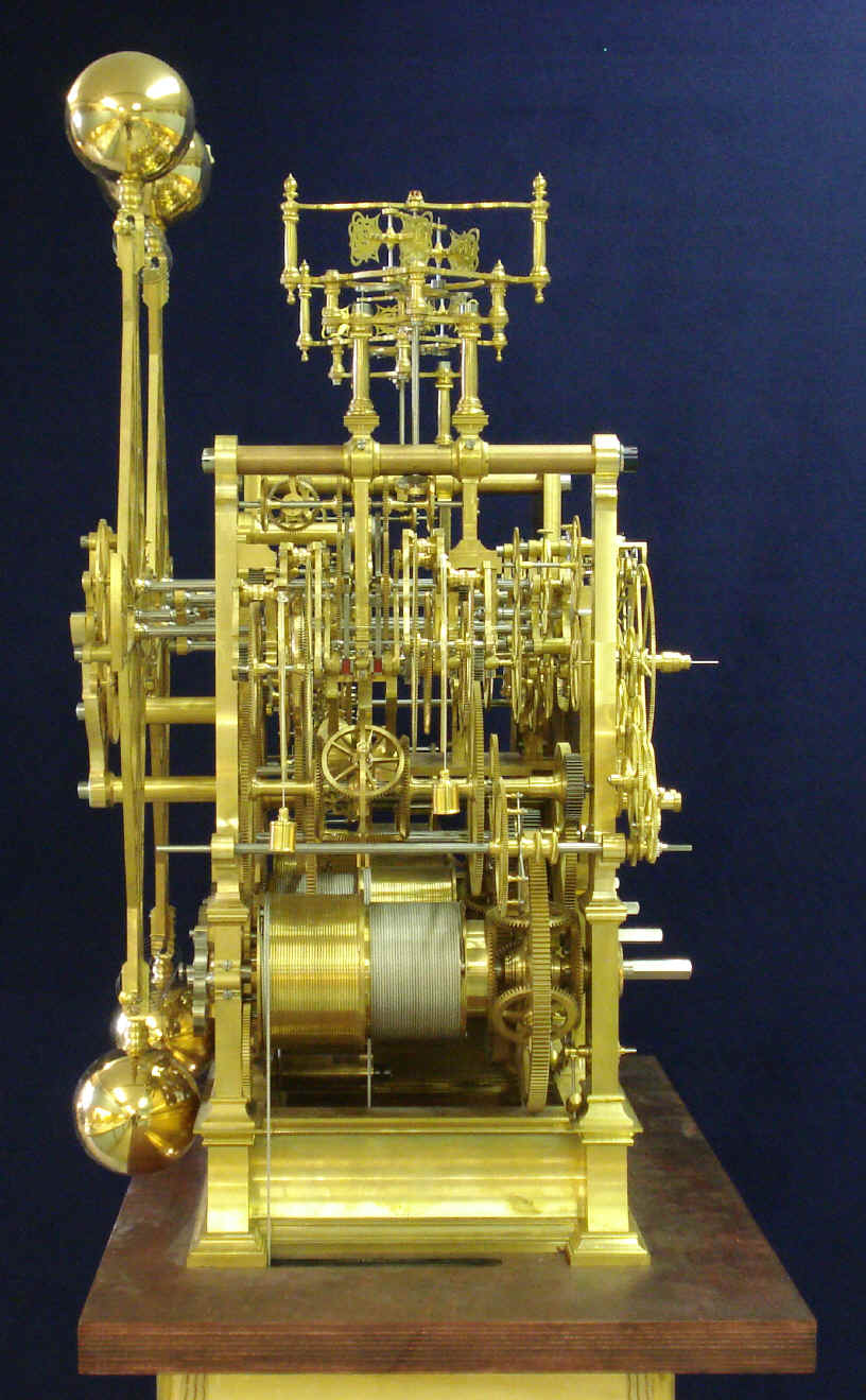
Next is the build up of the Robin remontoire, one of dozens of times this will be done as the parts are added and refined. Next is view of the central sub-assembly consisting of the three central pillar plates and containing the Robin remontoire, escapement and pendulum support frame.
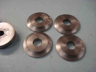
These series of photos show the fabrication
of the main movement frame decorative screw collars. These should provide a nice silver
backdrop to the blue screws against the gold-plated frame.
Below are four videos of the movement to date, these are linked from my channel on YouTube and you can go there directly though this link: http://www.youtube.com/user/fgtyc . When viewing be sure to click to the high resolution option of 720 from the standard 360 shown on the bottom right hand side of the control panel, (first four videos).
Below is a 23 minute video montage of the project from its design inception in late 2003, through the creation of the first design mockups and full scale model in July 2006. Fabrication from July 2007 through the midpoint of this project as of this month.
|