Assembly of fly to remontoire and going train, July 2008
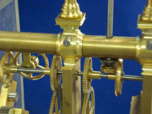
First photo shows a close up of one of the bearings with an end (dust) cap in the remontoire system. It should be noted at this point that a decision was made to use sealed roller bearings on all pivots that will encounter either a heavy load or a rotational velocity of over once per hour. The only exception to this is the remontoire and fly fans. This would encompass all of the pivots that are between the main plates as well as most of the time train movement. All of these pivots will get a dust cap on the front side and a plastic ring around the arbor pivot on the rear side to hide the roller bearing ring. These caps are made from a red plastic material that has been custom made to match the real jeweled bearing in the rest of the clock (see 12/07). All of the rest of the jeweled bearings, since they will be lightly loaded and have a slow rotational period, will run dry (no oil). This will greatly improve the reliability and longevity between required servicing. It is the breakdown, thickening and attraction of dirt to oil in a pivot that is the leading cause of problems. As Abraham-Louis Breguet said in the late 16th century, "Show me the perfect oil and I will give you the perfect watch". Second photo shows the remontoire cam locking pallet piece with cutout ready for jewel insert. Third, the bevel wheel fly drive system just below the upper column support. Remontoire star cams were redesigned in a thicker gauge. The larger pinions, like that on the left will have their cross sections dished to soften and stylize the appearance. Second photo shows more of the bevel drive along with the securing pins that fasten the cocks to the upper support column. These will later be trimmed down. Third photo the fly ready for attachment.
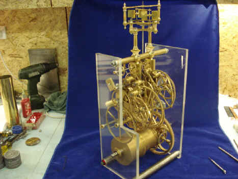
First a shot of the going train stripped of the remontoire. Note the differential drive in the middle of the second arbor. Next photo shows the remontoire components installed and the near-completed going wheel train. Technically the entire going train must also include the escapement and pendulum balance systems. In most conventional clock designs these components would be within the going train area. In this design they are driven by the going wheel train remotely.
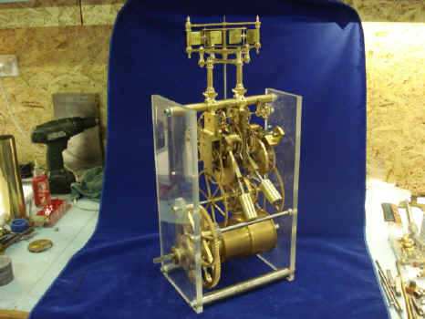
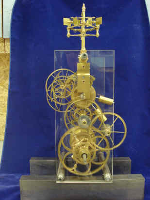
The next four shots show different views of the going train. The two large drive bevel wheels that will power the escapements are still solid discs and will be completed when all tolerances between them and to second fly are complete.
Two more shots of the front and rear going train elevations. A shot of the original mockup depicting the dual remontoire is shown for comparison. Notice how on one level the way the mockup faithfully gives a good idea of how the final product would look. On the other hand compare how much less of the final complexity was captured in the mockup as compared to the working movement. Even at this stage the wheel train is not totally complete; with about 95+% finished. The drive bevel wheels, cocks, remontoire main and counter-weights and main frame spacers have yet to be completed. Parts count for the wheel train 388.
Both fly fans positioned in the overall Plexiglas construction mount. Next a close-up of the barber pole twisting arbors that will be used for arbors that connect the fly and escapement assemblies. These arbors rotate fast enough to give the illusion of movement directionally along the arbor as one's eyes follow the twist. This direction will be from the origin, the going train toward the fly fans and escapement. Last photo shows the various jewels that will be used throughout the movement; 450 total. This was later increased by 100 jewels due to additional components and complexities encountered in the Grande sonnerie strike function, perpetual calendar and orrery. (updated November 1, 2015)
Astro_07-08_vid.mpg Astro_07-08_vid_2.mpg Astro_07-08_vid_4.mpg Astro_07-08_vid_5.mpg Astro_07-08_vid_3.mpg
|