Remontoire fly fan fabrication, finish up, June 2008
Work continues on the remontoire fly fan assemblies. We decided to use over-sized click springs for visual effect. There are two clicks, each offset by 1/2 tooth from the other so for each revolution one will hear twice the number of clicks as there are ratchet teeth on the wheel.
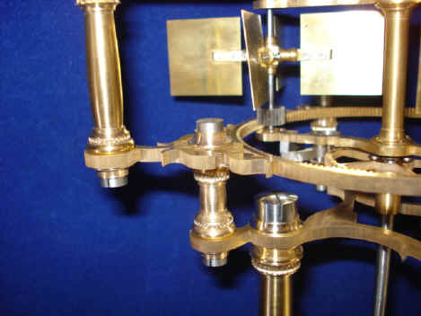
As we go along in the construction process, designs are made, changed and approved. The drawing below is for the lower fly fan support; the upper design (1) was approved. This will be what is the solid plate in the third photo. The second photo is the completed internal toothed fly fan drive ring with full filigree work.
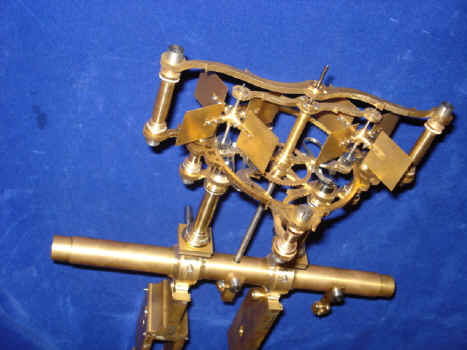
A shot of the completed fly from above. Note all of the fancy metal filigree cutouts which will be the hallmark of this project. At this point I noticed that the large cheese head screws looked too bulky and obtrusive. Also the idea of some sort of finial was considered for some or all of the screws.
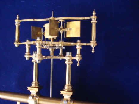
The solution to the screw problem was the addition of a turned collar to shorten the perceived tall edge of the screws. Additionally several finial designs were considered to substitute for the two uppermost screws and possibly some of the lower ones as well. Each fly angle can be individually adjusted to control the speed.
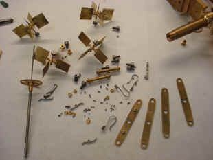
These two photos show the contrast between the near finished product compared to the original mockup model. Each fly assembly has over 140 parts. The original concept for the compound fly was conceived in April of 2004.
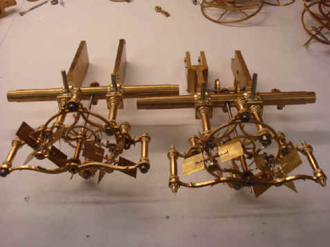
Shown are the two completed remontoire fly assemblies, one with only the screws and the other with some finials attached. The second video player selection shows the expected duration of the fly for each activation. The third shows an overview of the fly with a proposed finial design. A video of an assembly is important to gain a sense of perspective and proportionality that still photos cannot give. We use this tool throughout the project. Parts count for the fly fan assemblies 330.
Astro_06-08_vid.mpg Astro_06-08_vid_2.mpg Astro_06-08_vid_3.mpg Astro_06-08_vid_4.mpg Astro_06-08_vid_5.mpg Astro_08-08_vid_4
|