Main wheel clicks; begin escapement antifriction wheel assembly, August 2008
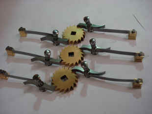
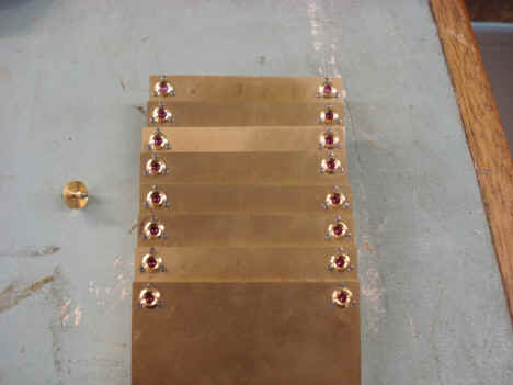
Below photos show most of the parts fabricated for the main wheel click springs. There are four identical sets for the four trains (eight clicks). Clicks will be arranged so each pair of clicks will engage the ratchet wheel in 1/2 tooth increments. This will give twice the number of audible clicks for each revolution of the ratchet wheel. It's the same system used for tall fly fan assemblies. Parts count for this system 52.
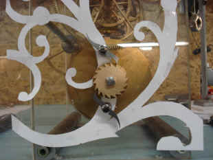
First photo showing proposed positions for the click spring feet. The frame outline is made from paper and pasted to the clear plastic frame to test where the feet can be placed thus determining the length of the click spring. Following photos begin the fabrication of the escapement system. It's interesting to note that in most conventional clock designs the escapement would be composed of maybe one or two dozen parts; the escape wheel, the escapement pallet, crutch and pendulum. In this project the parts count for the same components will be close to 700.
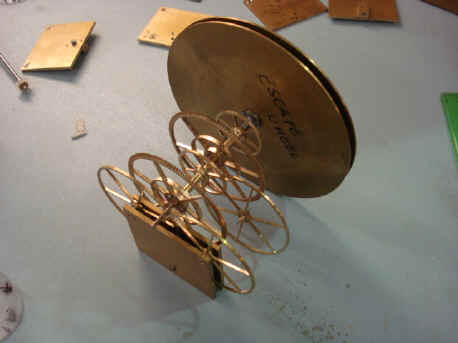
Numerous screws, all custom made. Next a shot of an initial antifriction wheel assembly.
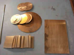
The eight support plates for the eight antifriction wheels that will compose the escapement support and drive system. Each antifriction wheel will run in jeweled chatons.
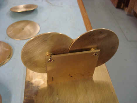
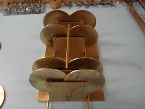
Antifriction wheels in the rough showing their positions. Next the fabrication of the bevel wheels that will drive the escapements.
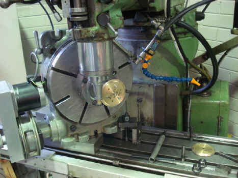
Further shots of the escapement bevel drive wheel fabrication.
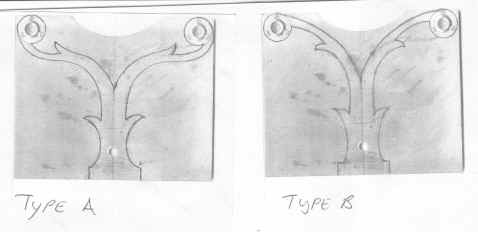
The design of this wheel is special. There is an additional inner ring that will be used as a thrust bearing acting upon an antifriction wheel to prevent the wheel from moving outward as is the case on any bevel wheel arrangement. Next two photos show progress in the bevel as well as antifriction wheel fabrication. The drawing is a a proposal of two designs that was submitted for the antifriction wheel cocks. I chose the first, 'A'.
During this time the going train was able to be put to a weight to see approximately what the power input would be needed to run the clock. The first serious design setback was now encountered. The fabricator had miscalculated the weight-to-duration needed to drive the clock by 100%. So the going (time) train which had been estimated to run for 8 days on a weight of 70kg (154 lb.) falling 3 1/2 feet will, at best, get 4 days. This is a major setback. But, in my opinion, not totally unexpected. This design has a huge number of mobiles, and is a large scale so there is a large amount of mass to be moved. Three feet on an eight day duration is a tough condition for even a conventional design let alone for this one. We will address this duration issue as the clock is made, but for now the going train will be four days with the remaining trains being 8 days - so far. This test is shown below.
Astro_08-08_vid.mpg Astro_08-08_vid_2.mpg Astro_08-08_vid_3.mpg
|