|
If the two animations are not synchronized, hit the back and then forward button to re-synch.
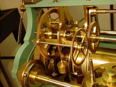
  Click here to view an animation of the Wagner rocking frame remontoire, it requires Adobe Shockwave player. There are three animations, click on "GOING" to see this one. COLLIN - WAGNER successor company to JEAN WAGNER, PARIS, FRANCE c. 1870 -1880s. 'Rocking frame' style remontoire. Invented by Bernard-Henri Wagner (Jean Wagner's uncle), France, c. 1850. Gravity driven, train type. 30 second cycle. Remontoire dimensions: 5"w x 3"h x 8.5"d. Below are some photos taken of repairs made to the remontoire. Some pieces were missing and broken when acquired.
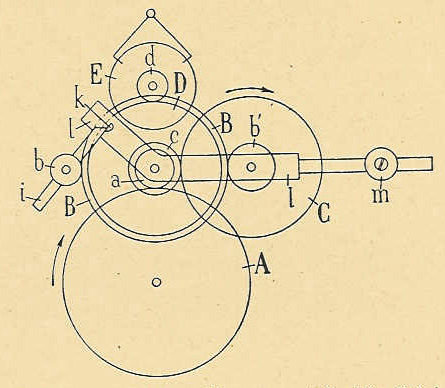
Text of voice over narrative below: What you see is a greatly speeded up sequence of events that in real time would take 30 seconds. All rotational directions are described using the left picture and would be reversed in the right. Notice first the small clockwise rotating arm behind the large wheel in the left picture, and center rear in the right which makes one-half revolution as soon as the frame reaches its lowest point. This arm is mounted to an arbor that meshes with the wheels connected to main weight of the movement. A cam and the remontoire frame are attached to an arbor that is supported and rotates freely between the two brass cocks mounted to the center of the upper movement support bar. Mounted on the frame is a freely rotating wheel and pinion at its front, a small weight hanging just behind and an adjustable counterbalance at the rear. The rear weight is set so as to allow the front weight just enough mass to drive the escapement. The cycle begins with the end of the arm at rest upon the face of a cam. This is the driving phase and lasts about 28 seconds. Throughout the cycle the clock train powered by the main movement weight is locked. During this time the fall of the small, cylindrical weight seen closest to the viewer is powering the entire escapement and pendulum. As it pulls the frame downward, it causes the remontoire pinion to mesh with the locked main movement wheel. This drives the wheel attached to the same arbor to turn clockwise and the adjoining escape wheel to turn counterclockwise. Since the left wheel is locked and the right remontoire wheel is free to move through the escapement, power is directed from the small weight through the right wheel and to the escapement. The cam is also rotating clockwise with the frame until the point that the end of the arm slips off its face. Now begins the recoil phase and lasts about 2 seconds. At this point the main movement train unlocks and the left wheel, powered by the main weight of the clock movement, begins to turn counterclockwise, meshing with the remontoire pinion. This happens at a faster rate than the wheel it is attached to is turning the escape wheel. This difference causes the pinion to ride along in the direction of the left wheel. Pulled by the remontoire pinion the cam and frame assembly rotate counterclockwise raising the weight upward while the arm makes one half revolution. To avoid jarring the remontoire, the speed at which the frame recoils is mediated by a small adjustable fly seen in the right picture. During this time the main movement is also advancing the clock in one increment equal to 30 seconds. This is demonstrated by the slight clockwise movement of the two pronged fork located on the takeoff wheel. The recoil continues until the cam face has moved back into its starting position, blocking the arm and locking the main movement wheel train again. All the while power is uninterrupted to the remontoire wheel driving the escapement and keeping a constant power supply throughout the cycle. The sequence should be seen as the small weight giving a constant source of power to the escapement at all times. The small weight’s potential energy is recharged periodically from the larger clock movement’s main weight before it exhausts its energy by reaching the end of its limited travel. The right wheel to the escapement is always being driven, the left movement wheel is always a driver, while the pinion always drives and is periodically driven. This is the principal of a differential gear system. The differential is the general mechanical concept employed in all gravity driven train remontoire.* The action you see, especially in the rotation of the escape wheel is necessarily distorted. The time the remontoire is driving is far greater than its recoil phase. So to make the animation fit into a reasonably sized file the driving phase was greatly speeded up while the recoil phase was slowed down a bit. * The Robin type is excepted. While it is gravity driven, it uses a flexible line or chain to achieve what is done via differential gearing. |