Upper frame, stop work and state-of-wind indicators - January 2010
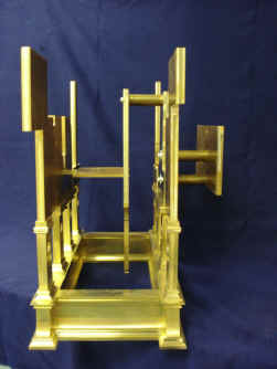
B finished the rough cutting of the upper
frame section in December. This is far more complex than the lower frame which is
basically eight pillars mounted to the base rectangular frame which hold the main four
wheels only. The upper section must deal with
the escapement assembly as well as the rest of the clock which needs several sub frames
both vertical as well as horizontal between the upper frame uprights.
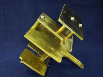
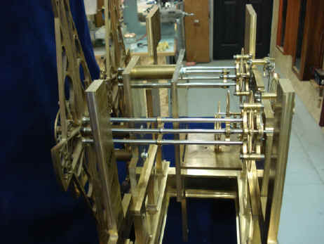
Now B fits the escapement assembly into the frames - looks like an impossible fit!
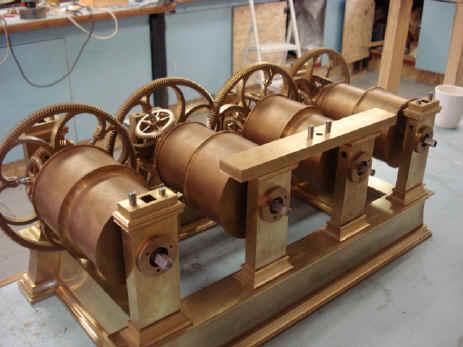
The lower frame now accepts the main wheels. The large bushes will later get a decorative chamfer on the outer edge.
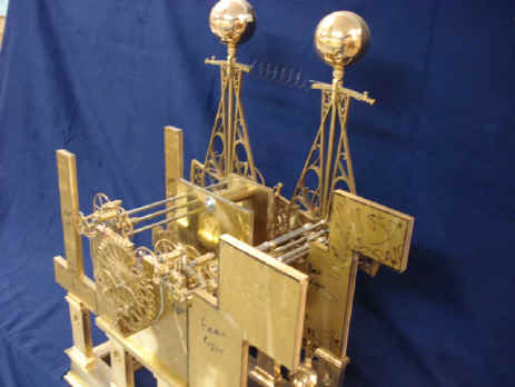
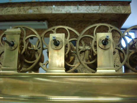
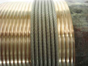
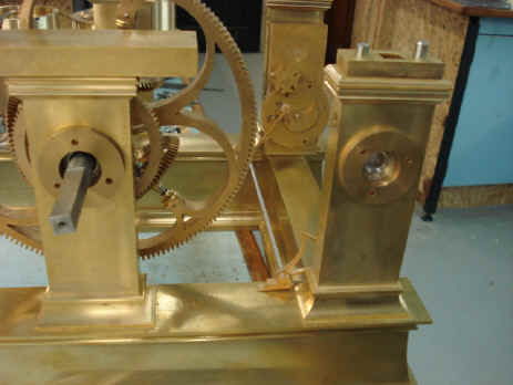
The winding barrels now receive their spiral groove. There’s more to this than meets the eye. While each
barrel’s great wheel all face in one direction, the body of the barrels alternate in
their orientation (see photos above). In order to allow all barrels to be wound in the
same direction, two barrels are cut with a right handed groove and two with a left hand
groove.
There was a problem however, with the associated clicks and springs. These were fabricated quite some time ago with the barrels and were some of the earlier subsystems built back in August 2008. This was at the time that we thought we would be using a conventional skeletonized plate and spacer frame design. We changed this design in March of 2009 and these clicks no longer work well within the revised pillar frame configuration. B sent some photos of how he tried to fit these in, below, none of which was satisfactory.
I suggested that he try a set of outboard mounts for the clicks to fasten to; with the springs attached to the pillar face. I also said that we may want to change the shape of the springs from the straight to a curved design similar to that used for the remontoire fly fan clicks. The third photo shows the proposed mount in a brass-painted wood set upon the brass pillar. Either way the clicks themselves are still too large and will need to be cut down somewhat.
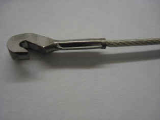
Before moving on from the winding barrels, B devised the cable
attachments. Once this was done failure tests were performed to make sure this attachment
would safely exceed the weight's mass. Several
‘test-to-fail’ measurements were made to be sure that this system works. It
failed at 132kg / 290lb or 6.6 times the anticipated movement weight of 44lb.
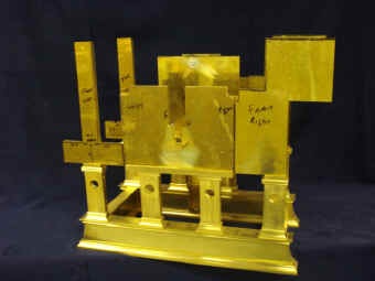
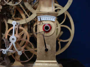
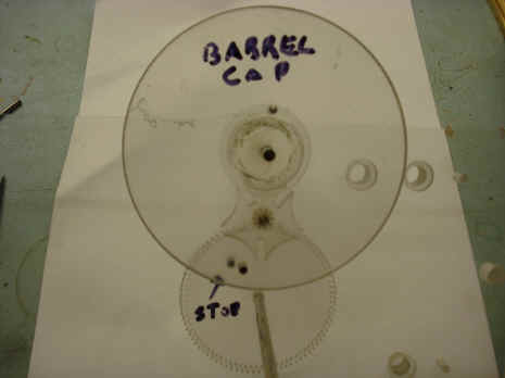
Next began fabrication on the stop-work. The purpose of this device is to provide a positive stop to prevent over-winding or the weights crashing into the winding barrel. We also will have the same stop on the way down so the weights will never actually touch the floor. This prevents scratching the bottom of the weight or floor and slack lines. At this point I realized, that the type of stop-work using a Maltese-shaped Geneva stop could also be used to generate an up/down or state of wind indicator. With this feature the person winding the clock will not have to bend under the surface of the clock stand to see when the weight is nearing the upper stop. While the stop itself should suffice, this eliminates any accidents from too much winding force on the stop. Because we are using epicyclical maintaining power, we also have a great mechanical advantage on the winding square, so such an accident is a real possibility. Besides such a device adds to functionality in the ability to see a pointer moving as one winds the clock and slow down and stop before hitting the actual stop-work. Also one additional complication! The only fly in the ointment comes with the equation of time kidney cam being in front of the time train state-of-wind indicator, third photo below. The dial is still legible, and B insists that the actual parts in metal will be far thinner and delicate, so as to give less of an obstruction.
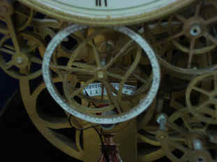
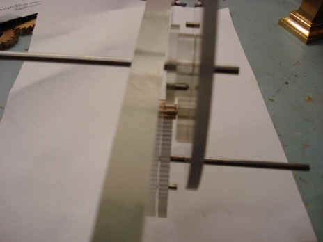
Below is a drawing showing both the stop-work and the snail and associated following arm to drive the state-of-wind indicator. The rest show the mockup in wood of the proposed linkages for the state-of-wind indicator. The two sector gears drive the dial pointer.
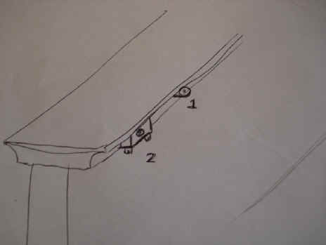
The photo below shows a weakness in the design. The bearing blocks for the long arbor that carries the stop-work information from the rear to the front of the frame to be read off the indicator dial is supported by these blocks. It looks too ad-hoc, like a snail crawling across a flat surface. It abuts the pillar's foot in an awkward way and disturbs the clean surface. The next photo shows a drawing that we came up with after some discussion to eliminate this. We had to come up with a design that also allows B to assemble this part without having to part the frame base. Bearing mount #2 was chosen and will be recessed into the inner molding.
B now makes the stop-work assembly in plastic to test for functionality, a process which has been repeated many times for the movement's various mechanical subsystems.
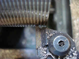
Now begins the fabrication of the stop-work parts. The next six photos will show the steps in making the Maltese-shaped Geneva stop. The first photo shows the four Geneva stop blank discs to the left. First the five rectangular slots are cut into two blanks and finished slots are shown in the third view. The wheels will later be spoked out.
Next the fly cutter shapes the circular 'wing' of the five lobed Geneva cam. Two finished Geneva stops in the last view.
Notice in the video below, no safety goggles or protective gloves! B did suffer a small hand injury after the test. Safety first. Astro_01-10_vid
|