Cable hooks; Stop work; begin power reserve indicators - February 2010
The photos on this page show the intricate steps employed to make
a lowly, simple part like a cable hook or an innocuous assembly like the Geneva stop
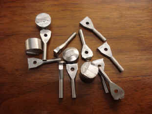
works. Below B fabricates the weight cable hooks.
Each one has the slot cut by a hand saw.
B now cuts the custom slot needed for the
hook and cable to rest perfectly within the barrel with no strain on any portion of the
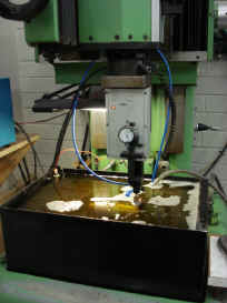
cable or hook. We discussed several options to minimize cable strain. A spark erosion
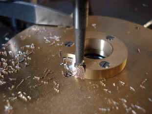
machine is used to make the complex shape needed for this. The second photo shows the spark erosion
template used to cut the custom contour on the barrel. The actual process takes place with
the part completely submerged in the liquid medium.
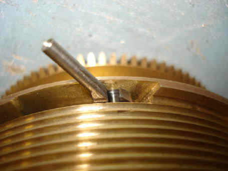
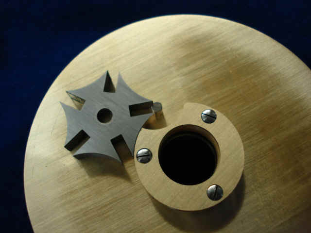
These photos show how the hook is positioned to minimize stress from any sharp bends, yet still make the hook easily removable. Note the center hole contains a sealed ball race.
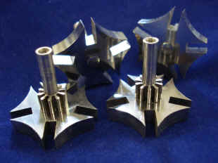
Next begins fabrication of the stop work.
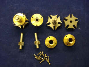
Shown are various parts involved in the making of the Geneva stop system. The Geneva cam runs in sealed ball bearings.
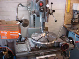
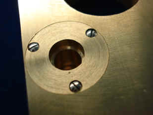
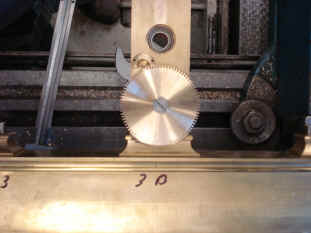
Below is the blind hole installation for the Geneva stop bearing since the opposite side of the pillar must remain unmarked. The fourth photo shows where B had to machine away part of the inner base molding to accommodate the snail drive wheel. It was necessary because this snail wheel is a part of the power reserve system which was added to the project only in the last few months, and after the the lower frame assembly had already been fabricated. The snail wheel will later be spoked out.
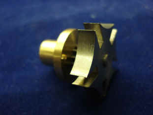
The snails are now cut. These will move the lever roller, which in turn is connected to the indicator hand.
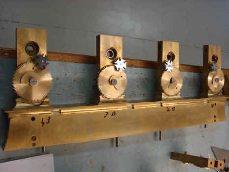
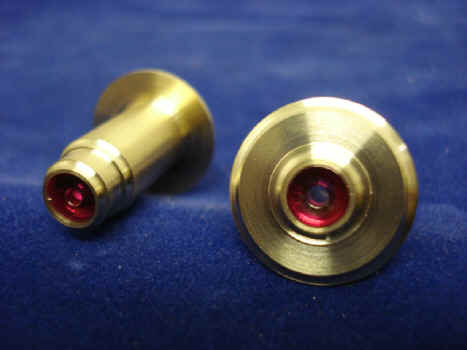
Shown, left, is the completed roughed out Geneva stop and power reserve snail drives which are all mounted to rear set of lower pillars. Right is a view of the front and rear of the jeweled bearings for the power reserve hand.
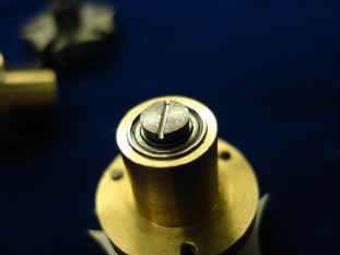
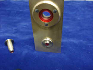
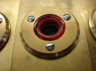
First photo shows one of the lower front pillars with both the main winding barrel bearing as well as the power reserve hand bearing. The larger, barrel bearing is not jeweled, but is a sealed roller bearing. To make this look similar to all of the real jeweled bearings, like the smaller one below it, a red plastic insert is placed in front of the ball race rim, second photo. Last photo shows the rear of the pillar plate and the opposite end of the power reserve bearing. Note the additional decorative machining on both this and the rim of the main front bearing rims. The silver screws will later be heat-treated to an electric-blue color.
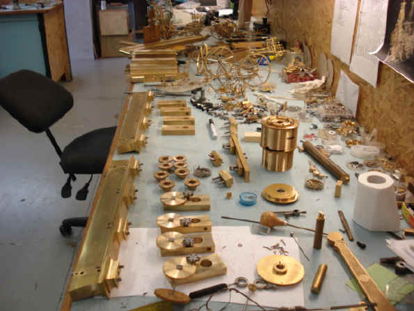
Two photos of the 'exploded' movement to date. How does B keep track of all these parts?
|