|
Miscellaneous projects; preliminary mockup for planisphere module - January 2018 This month Buchanan goes through some "housekeeping" chores. There were a few remaining items for the sun /moon rise-set module. The escapement needed some adjustments, the pendulum springs were remade, a set of mockups were made for the remaining enamel dials that had yet to be created for the clock. Preliminary designs for the base and plinth for the planisphere are formulated. Next month we begin the planisphere module.
These photos show the various parts of the escapement that have been
disassembled to correct for an imperfect motion between the upper and lower
pallets. Buchanan writes:
I have also been working on the balancing of the pallets. I have identified
two areas that need more attention. The weight of the remontoire star
wheels is to great, when they are released the sudden deceleration gives the
escape wheel a small jolt. I can drastically reduce the weight of the star
wheels but that requires a complete teardown of the clock so it will have to
wait.
The other is pivot drag on the lower pallet which stops bounce but also
drags the pallet away from the escape wheel during the impulse . I think I
have a solution for this. I am doing a little homework on it first.
I am also looking to see if I can introduce some drag on the upper pallets.
We have the opposite problem here. They bounce for too long.
These two photos show the bezel along with the tellurian dial bezel
being machined in the mill for fit with each other as well as clearance for
the moon indicator.
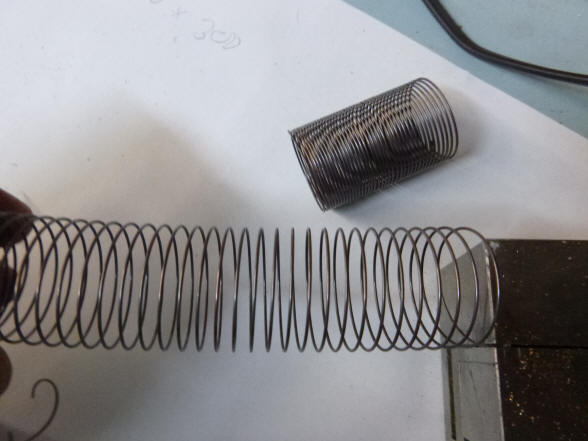
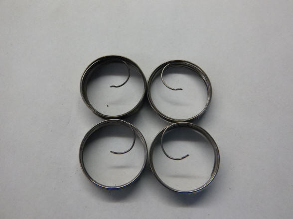
Now Buchanan replaces the Ni-Span-C® wire originally installed in September 2016. The wire is wrapped around a form to create the desired coil diameter and heated to form the coil. Then the coil is heated to 500 ° C, (932° F) for five hours. This is to harden the springs further improving their temperature coefficient to nearly zero as we later found in our tests.
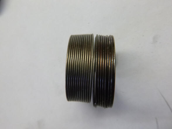
The first photo shows a failed attempt. The coil looked good when relaxed, but did not open up evenly along the entire length when stretched. The second photo shows the coil re-wrapped by machine, resulting in a more uniform and tight winding and with an adjustment in the temperature produced the desired result.
The spring now opens evenly and in the relaxed state
stays even, see spring in background, giving
the desired result in the first photo. The heat treatment results in a black
scale on the surface, so Buchanan uses a vibratory polishing machine to remove
the scale and smooth the coil surface.
The coils now have a
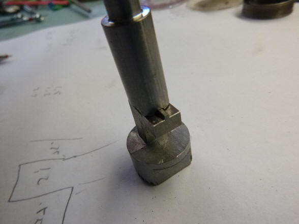
smooth, refined surface, first photo. Next Buchanan creates a die set to create
the shape need at the end of each spring to receive a small ring which will
attach it to the pendulum.
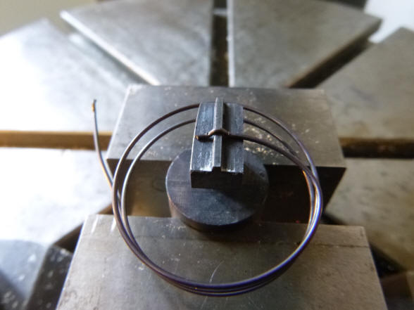
The mated die set is shown. Next the die being used to press the correct shape onto the wire end.
The first photo shows the face of the lower die piece, and the second photo the coil end piece with the proper form to retain the spring. This design allows one to quickly attach and remove the springs without disturbing any other adjustments.
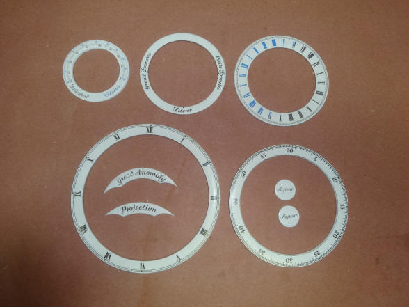
The completed spring set consists of two pairs; each for the upper and lower pendulum positions. Buchanan says that these springs are producing a very good rate vs temperature change, so the clock has very good temperature compensation. Next photo shows the final design work for the remaining enamel dials that have yet to be made in China.
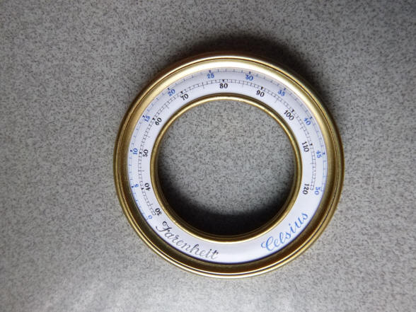
The dials shown from the upper top row left are the thermometer dial, strike control dial, world time and demo dial, lower row, the sidereal hour dial, next the inner sidereal minute dial and inside each dial the sector dials indicating the variable differential controllers mediating the moon's orbital corrections: Great Anomaly and Projection and then the two repeat disks attached to each side of the 'pull-repeat' button. The next diagram shows the artwork for the thermometer.
These two photos show the thermometer dial within the mockup bezel and that bezel mounted within the context of the clock movement. ----oooOooo---- Buchanan now turns to the fabrication of the planisphere
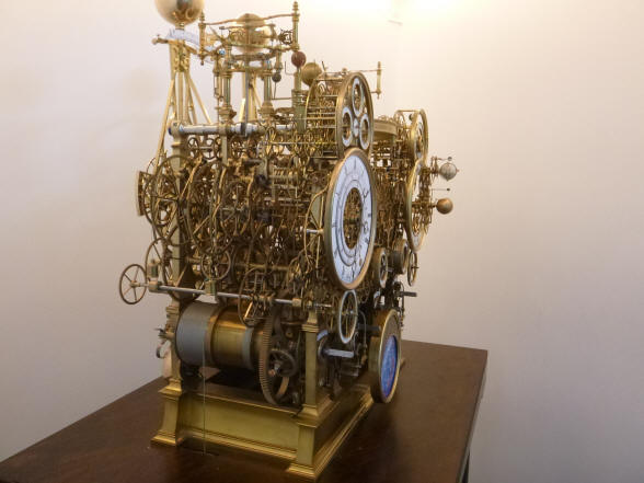
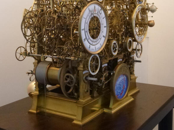
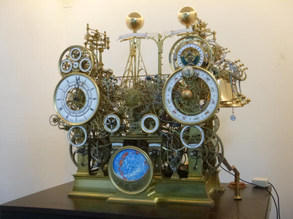
The first thing that needed to be determined was how the planisphere dial would be attached to the clock. The simplest design would be to attached the dial to the frame with pillars. This looked too much like the dial was "tacked onto" the clock. The dial as seen in the first photo seems to dangle over the main base frame rail; unlike the other dials that are more closely incorporated into the rest of the machine. One observation to be made in the first photo is the placement of the dials in the first photo; the recess of those dials in relationship to each other. The two large main dials are positioned furthest forward, and the two between them a bit inward, with the two composite dials above and the two smaller dials directly below a bit more recessed. The planisphere, is on the same plane as the the two main dials. The slight differences in depth of the dial set adds to the visual interest of the clock.
The next design created a base extension and plinth that held the dial with the same curvature as was used on the main base rail corners. That plinth rests upon a platform that extends from the front base rail and duplicates the base decorative design. The first thing that needed attention was the gap between the plinth and the base. The gap made the plinth look less than elegant.
The gap is now filled with a curved wall. Note that the upper decorative bead is also extended. The next photo shows the overall view. I thought that the plinth looked too "heavy" in relation to the dial the dial being like a face that was attached to a neck that was too thick. While I understood the rationale of having matching curvatures between the base corners and the plinth, those curves were too heavy in the context of the smaller area encompassed by the the dial plinth.
The next trial involved a tighter curve. Notice how the curve ends below the top of the base rail. While this was an improvement it still did not eliminate the blocky nature of the plinth.
The curve is now appropriate but the dial still needs to be melded to the front base rail. The gap between the dial bezel and base needs to be eliminated altogether.
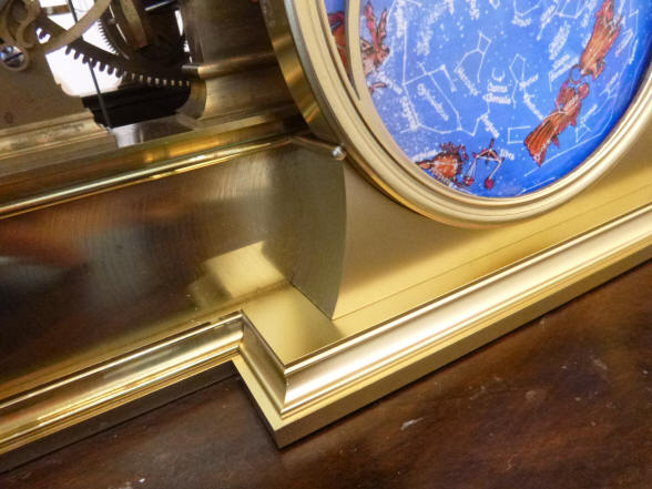
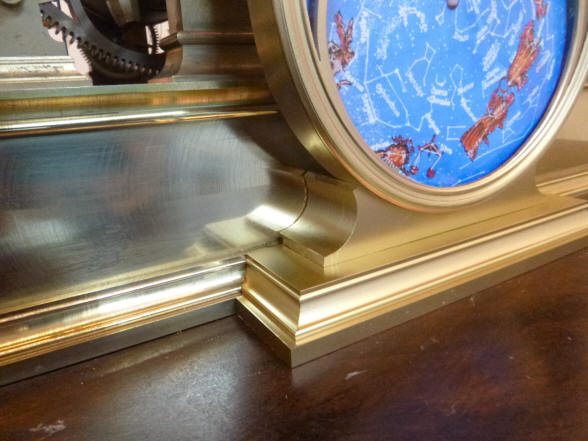
Now the plinth is complete. It blends seamlessly into the existing frame. Notice how the top decorative frame beading is continued along the plinth extension wall as well as the additional reveal created at the top of the plinth's curve termination. The plastic planisphere plinth and base mockup parts are so well made and finished off that they blend in seamlessly with the metal frame base rail. Buchanan's skill in making the hundreds of mockup parts throughout the project has contributed immensely to its success. At the beginning of the project we had parts that were initially fabricated in metal inserted into the wooden mockup machine to test for fit and function. Over time less and less of the wood mockup was needed until the roles were reversed in the last several years and individual mockup parts are now inserted into the machine made from metal.
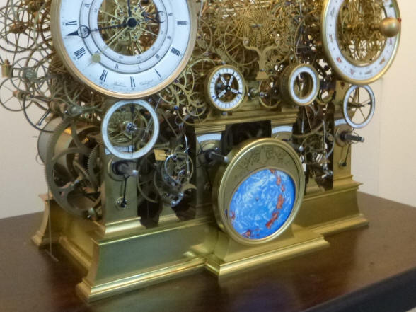
These photos show the final plinth design. Notice anything different?
We have decided to rotate the dial 180° from the original position. I think this brings the blue dial area closer to the other dial work; achieving a more integrated and balanced look in the clock and allows the brass area of the dial mask to blend in with the plinth and base rail. Next month we begin the fabrication of the planisphere complication.
Buchanan writes:
Looking
through the early photos you sent me about what you wanted; it is
interesting to see now, how much we have managed to incorporate. I remember
studying photo 133 to see how he made these frames. I have not thought much
about this photo since then but I d think it influenced our frame design a
lot subconsciously.
|


![]()
![]()
![]()