|
Begin planisphere module - February 2018 This month Buchanan begins the second to the last mechanical complication on the machine, planisphere. The last will be the orrery.
The first two photos are the
initial axis design for the nesting of the star plate and sun hand
indicator. The third is an initial gear layout. Notice how Buchanan uses
paper cutouts for the gear arrangements. The fourth photo shows the
initial gearing for the sun hand precession. In this example the hand
remains stationary when the plastic disk below (not easily seen in this
photo) is rotated. This was made to demonstrate what later will have a set
of gears that will allow the hand to have an annual precession across the
sky. In other words, the star plate rotates once in a sidereal day with the
sun rotating once in a solar day. A sidereal day is about 3 minutes, 55.9 seconds
shorter than a solar day thus after one solar day the sun hand will be just
under four minutes ahead of the star plate. So if on January 1st
both the sun hand and a point marked on the star plate are aligned at twelve
o’clock, the sun hand will advance just under four minutes each day and
after one year the sun hand will return to its twelve o’clock position
aligned with the mark on the star plate. This is the representation of the
sun’s precession across the sky as it relates to its position against the
stars.
The first photo shows
the gear set needed to drive the planisphere from the movement. The drive is
a sidereal input for the star plate. The second photo is a print out from
the on line compound gear calculator, a real labor saving device from the
sources we used initially in 2006 for gear calculations. Buchanan writes:
I have tried a second sidereal gear train to the first. The first had gears
that were too small to cover the distance between demo output and the
planisphere so I worked out a larger set but these would not fit into the
available space so I am now looking for an intermediate size gear train. I
have found a workable gear train. There are a few clock parts in the way,
here or there. 1 second in 336,000 years should be acceptable. I have a 12
gear train that is 1 second in 24 million years. I would have liked a more
arty set but the combinations do not oblige.
Tomorrow I can fill in all the final details.
I had a three day run on the timing machine and there
are good temperature cycles each day but no sign of any temperature error at
all!
This last sentence is good news for the accuracy of the clock; the Elinvar
springs are doing their job.
Buchanan writes: In the attached photos, the pens are pointing to the edge of the bezel next to the winding squares. The first photo with the small gears is the sidereal train and the other, with the big gear is the time train. This will be in front of the sidereal train. So you will see from the front of the clock 7 gears and 8 will be hidden. The two faint circles at top left and top right are the 24 hour dial and the thermometer.

Buchanan
writes:
I have the design complete and everything is fitting on well (after a little
juggling).
I have had to add one more large wheel in to push a gear train backward so
as to be able to fit in the support frame. It will give us a little visual
complexity. I will ink In the drawing now and then I can start cutting metal
tomorrow.
Buchanan writes:
I have all the gear sizes worked out so am now
preparing blanks,
I hope to start cutting gears on Monday,
I may possibly first start the plinth and support frame for two reasons,
firstly I have lost one of my gear cutters and am waiting for another from
England. And secondly I need to stress relieve the brass sheet for the gears
before I start.
This is the final drawing. Buchanan is now ready to cut metal.
Buchanan writes: I have all my blanks roughed out and stress relieved. I hope to have them all machined to size by tonight. Some are old gears that I am repurposing; I have cut doubles sometimes but never seem to use them. I am also working on the big blocks for the base, Brass on the left and plastic on the right in photo.
Buchanan writes:
I have the disc for mounting the enamel on roughed out, and, a method
thought out as how to mount the enamel onto the brass dial plate. I also
have the two main bearing sleeves complete with one gear attached. Next is
the collet and centre shaft for the dial plate and then the main frame for
the planisphere. Then the process of mounting the drive trains and floating
them on as much air as possible.
Buchanan writes:
I have the main frame with the centre bearing fitted. The clearance’s for
the Fasoldt’s have caused a little trouble and some juggling but all is
working out well now. The next requirement is the attachment to the main
frames. I will have to mount the base and mainframe properly before I
go any further because everything else depends on the fixed position of the
centre shaft.
Here we see Buchanan
has been able to move the planisphere disk forward enough to clear the
Fasoldt strike train detent whips, see video below. But another problem has
surfaced. The main barrel winding arbors are too close to the planisphere
disk. They just barely clear the disk and any misalignment of the user
inserting the winding key for the quarter strike train will cause damage to
the edge of the planisphere bezel. The diameter cannot be reduced since the
enamel star disk has already been made. The winding arbor on the other side for
the celestial train presents the same problem. It looks like these will need
to be extended forward so the key will fit before it reaches the vertical
plane where the planisphere dial bezel is located.
Buchanan writes:
I have the pillar holes drilled in the main frame. I had to make a
special jig and a custom clamp. It feels like sacrilege to drill into a
running clock with a 3/8 inch drill! The two stainless steel pillars are
almost complete. I will have a lever each side of the dial, but inside, to
lock this frame in place. The pedestal and bezel will mount on this main
frame and come away as a complete unit. This is truly an
example of “measure twice cut once”. Here Buchanan secures the planisphere
support frame to the clock base rail. If a mistake is made here, the main
clock frame is ruined! Fortunately everything went to plan. It’s interesting
how sometimes a critical fabrication step devolves into the use of a simple
home drill.
Buchanan writes:
I have the spiral bayonet fittings almost complete. The spiral on each
pillar is opposite to the other. So by lifting the clamp levers on each side
the planisphere is released and by pushing both clamp levers down it clamps
both pillars. I must make recesses in the frames for the clamp levers and
the pillar screws and the clamps will be finished. Then I can start on
the gear train.
Deryck writes:
The clamps are almost complete. The machining was a little tricky as
there is a raised ridge around the pillar hole that runs in the groove in
the clamp arm so as to retain it in the recess to make installing easy.
These two photos show
the planisphere module mounting bracket secured to the clock base frame from
the outside and inside.
The first photo shows the male and female
components of the levers that allow the user to quickly mount or dismount
the planisphere module. Next a close up of one of the levers.
These two photos show
the pair of levers that secure the planisphere to the clock frame. The
photos show the unlocked and then locked positions.
This wheel is the drive
for the planisphere disk. It is one of the largest yet finest wheels in the
machine with 516 teeth at just under 5” (12 cm) in diameter. Look at the delicacy of
this wheel; it could easily be crushed in one hand.
The wheel mounted to the planisphere frame. It is one of the largest and most delicate examples of Buchanan's wheel cutting artistry. It's unfortunate that this beautiful piece of wheel work art will be largely hidden forever after the planisphere enamel dial and bezel is installed, so look at it now!
These photos show the sun hand drive. One can see some conflict where the center of the drive wheel is butting up against the rear plate rim of the thermometer module in the last photo.
The rear plate of the
thermometer module shown in the first photo is further skeletonized in the
second. This was needed for both esthetic as well as the need for clearance
for the sun hand drive.
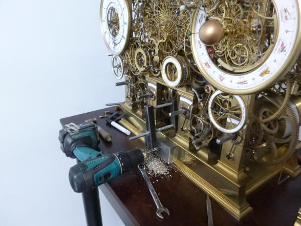
These photos show the
build out of the thermometer unit and the sun hand drive. The thermometer
unit was never a stand-alone module and was always mounted to a frame that
held an intermediate wheel connecting the demonstration crank to the
planisphere through the sun hand drive as well as the tellurian. |


![]()
![]()
![]()