|
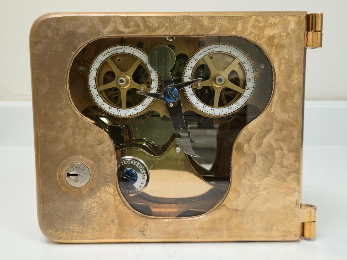
Sargent & Greenleaf, Rochester, New York - 2 movements, OEM variant Model #2[3], change over from rollerbolt to cello bolt design and movement update from v.3 to v.12, 1875 to c.1917
This time lock began as a Sargent and Greenleaf (S&G) Model 2 v.3 c.1875, using the rollerbolt dogging device first introduced by S&G in 1874.The case serial number is 328 and movement #330. Upon close examination it is clear the changes made were made by the manufacturer and not a secondary market retrofit. The case design which has a trefoil window was unique to the earlier S&G locks using their rollerbolt design. Until this and one other example which was seen concurrent to this one, this author has not seen a case designed for a rollerbolt converted for use with the later developed cello-bolt. Why make these changes? S&G first introduced their rollerbolt design for use in their Magnetic Combination Lock in 1866. The purpose of this was to isolate the combination lock's wheel pack from the lateral pressure of the door bolt, ensuring that the bolt handle cannot be used to pressure the tumblers and give away their position. When the correct combination was dialed in the bolt turned to to align a square cutout section with the side of the case freeing a portion of the safe boltwork to move into the case; allowing the safe to be opened. ¹The first version of S&G's time locks also used a rollerbolt to either block (dog), or when aligned properly to the case opening, allow a sliding bolt from the safe works to enter the timelock case and open the safe. All time locks use some form of blocking device to keep the safe from being opened even if the correct combination is dialed in until the time lock has at least one of its redundant movements wound down to zero. This condition known as the lock being "off guard". When all of the movements are running and therefore greater than zero hours the lock is "on guard". There were locks produced with only one movement but these lay outside the scope of the example being presented here.
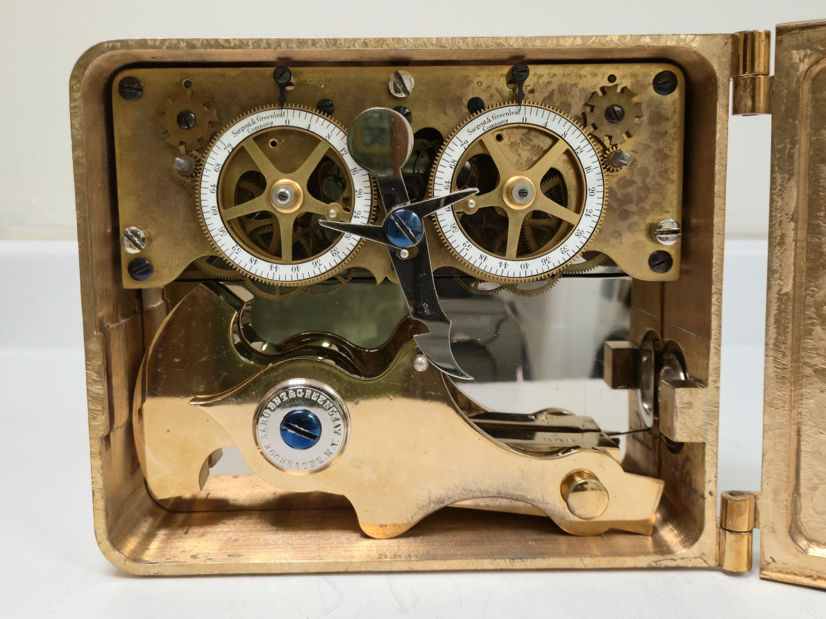
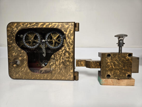
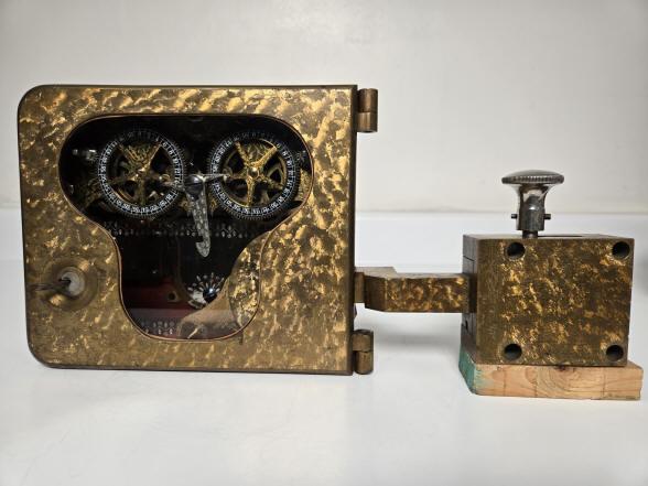
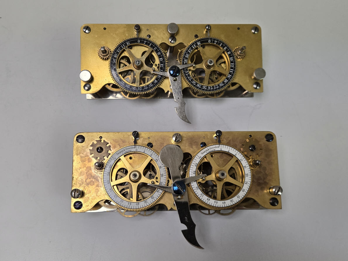
Sargent's rollerbolt was quite well suited for use in a combination lock, but its use in the Model 2 time lock required the addition of an auxiliary bolt, attached not to the door, but to a moving part of the boltwork. Closing the safe meant opening the auxiliary bolt by pulling up on the locking knob and pushing the bolt to the right, left photo, winding the time lock movements, hooking the rollerbolt up, (locked), and closing and locking the door. As the the boltwork closed, the outer sleeve of the auxiliary bolt would move with it while the flat end of the inner piece would abut a fixed part of the door. The sleeve would slide until until the auxiliary bolt snapped shut, time-locking the door. This would restore the proper extended length to the bolt and when the time lock went off guard, and the correct combination was dial in, that extension created by the auxiliary bolt would slide into the case, right photo .²A new bolt dogging design was introduced in their Model version 6 in 1877. It was nicknamed the cello-bolt because of its outline is similar to that instrument, see second photo near top of this page. The cello-bolt is a two-piece design, with the front handle portion made of bronze and the actual bolt portion in the rear with nickel plating. The large pivot point at the left of the handle allows the handle to be lifted onto the drop lever while while door's boltwork extension is still inside the case. When the door is closed, the boltwork extension withdraws and the rear part of the cell-bolt is lifted up by an internal leaf spring, blocking the boltwork. This two-part leaf-sprung design allowed for a one step setup of the boltwork and is simple, secure, and inexpensive and would be modified many times depending on case design and size, surviving well into the twentieth century.³ It is this innovation that was retrofitted into the example illustrated. S&G made updates to the movements mainly to reflect the increasing demand for longer duration time locks. The first Model 2 time lock in 1874 had a 46 hour duration and by 1886 this was increased to 72 hours. Other later time lock models in the S&G line had movements up to 120 hours. Changes made to retrofit the movement illustrated here: Updating of the movement by S&G to reflect newer technology and customer demands was common. The Model 2 was in production for over fifty years and time locks were expensive, so the updating of older locks would have been expected rather than new purchases. We know that the movement started out as a version 3 in 1875 because the movement front plate retains the leaf and vine design which was discontinued with the introduction of their version 4 in 1876. The serial numbering makes it unlikely that this was a version 1 or 2. At the time of production, the movement would have had black 46-hour duration dials. There would not have been the Geneva stop work on the front plate, which was introduced in version 10 in 1880. The lock duration increased from 46 hours to 48, version 10 and 66 hours, version 9 and then 72 hours in their version 11 introduced in 1886. The white dial color replaced the black color in 1878. At that time there was no logo designation on the dial work. Before 1896 S&G was a partnership, afterward they incorporated and the dial work showed Sargent & Greenleaf Co., later in 1918 the company reorganized and the the dial work showed the designation of Sargent & Greenleaf, Inc. The dial work logo makes this conversion no later than about 1917 .S&G introduced jeweled pallets on the escapement in the version 4 in 1896 which this updated movement has. The screws which secure the movement within the case were originally supplied with decorative threaded 'button' caps that screwed over the slot heads of the retaining screws for a more finished look. Around 1910 S&G replaced these with nickel plated slot-head screws doing away with the separate caps. The drop lever design with the round head extension used here was first introduced in the version 8 in 1878 and was originally elaborately engraved. the plain finish seen here corresponds with S&G eliminating all engraving on their lock components in 1910. This also applies to the plain rear silver plate behind the drop bolt as well as the drop bolt itself. Given what is known about the dating of changes that S&G made to their movement design we can date the retrofit of this original movement from 1875 to somewhere between 1910 and 1917, these being bracketed by the elimination of all engraving and the last date for the logo on the dial work. Compare the two movement changes in the photo below. The one on top is from an unaltered rollerbolt lock with movement #535. The one below is the conversion movement #330. The conversion is an older movement than the unaltered one.
One can see the many changes that were made to the lower movement. 1. Screws that secure the movement to the case do not have the decorative 'button caps, fasted to the three screws. 2, The color, duration and logo of the dials. 3. The addition of Geneva stop work. 4. Updated drop lever design without decorative engraving. The apparent difference in the size of the movements is a result of the photographic angle, they are identical and would be interchangeable between the cases. What look like blotches on the movement plate are the leaf and vine engraving that may have been rubbed to "update" the look. Changes made to the case for the conversion from rollerbolt to cello bolt design: The case is serial numbered 328 and has gone through extensive re-machining to accommodate the changeover from a roller to cello-bolt design. many areas were drilled with new holes and other holes were filled. The right side of the case where a square cutout was originally located for S&G's custom auxiliary square boltwork to enter the roller bolt was filled and a round hole with decorative collar was drilled into that location to accommodate the normal cylindrical boltwork found on safe safe doors compatible with the redesigned cello bolt.
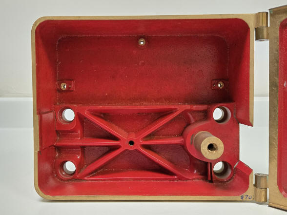
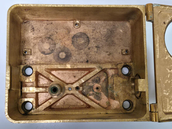
The first photo shows the unaltered rollerbolt case #531. The next is the altered example #328. Both started out as a rollerbolt design. One can see the mount upon which the rollerbolt rotates has been removed and the entire web casting has also been milled down about a quarter inch. The square cutout for the rollerbolt has been filled in and a standard hole with decorative collar has been put in its place. The infill witness marks are clearly seen in subsequent photos. Also, the safety block used in the cello bolt design has been added adjacent to the in-filled area with the new hole. A new mount has been added to the left side for the cello bolt mount. The hole in the center of the web in the left photo is for the screw to secure the chrome rear plate. In the right photo a new hole has been drilled and tapped for a new plate. Note that the safe door's bolt work enters the case from the same location on the hinge side.
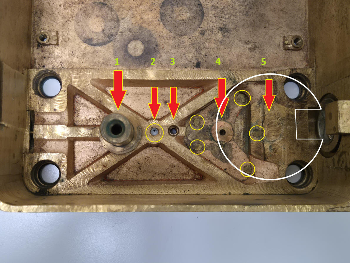
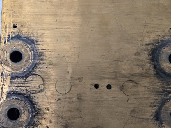
This photo shows the numerous alterations made to the case. 1. is the retrofit mount for the cello bolt, 2. is the old hole for the original rear plate screw, 3. is the hole for the new rear plate screw, 4. is unknown, 5. is the area filled in where the original roller bolt mount was located. There are five circled areas that indicate other filled in holes. Looking at the unaltered case cited above there are no holes in these areas so the reason why these holes existed and thus later being filled is unknown. The white circled drawing represents the location of the original rollerbolt centered on the now removed mount.
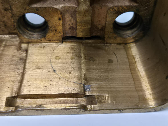
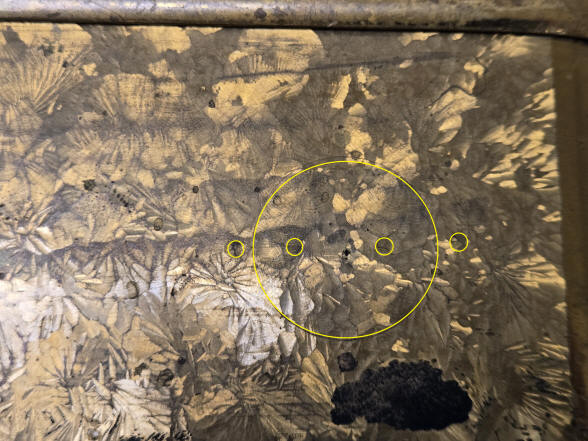
The left photo shows the various filled in holes as well as the two holes that were used to secure the old and replacement rear plates. The large hole to the left is the replaced rollerbolt mount while the one to the right is the retrofit cello bolt mount. The right photo clearly shows the square opening now filled to accommodate the round hole and collar used with the cello bolt design. The outside surface of this retrofit matches perfectly the damascene of the surrounding case. This indicates that the case was resurfaced completely after the retrofit.
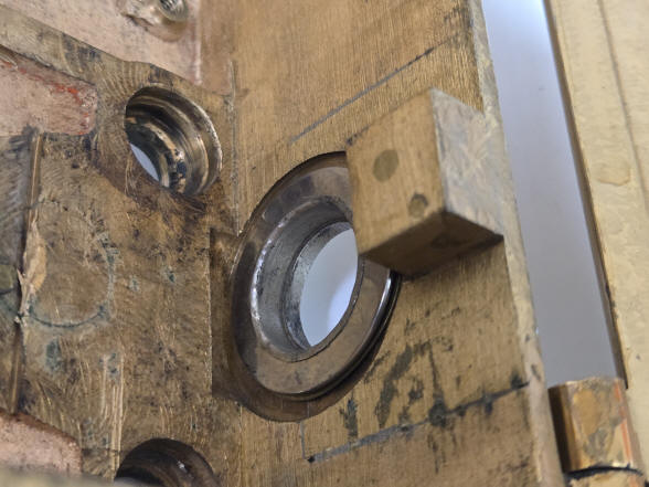
These two photos present a conundrum. Here is evidence of a hole that would have had fitted the standard round bolt hole and decorative collar similar to the retrofit on the hinged side. That design required a hole drilled through the case with a larger diameter circular inset milled into the interior to hold the collar. Thus one sees a smaller hole on the outside of the case in the right hand photo with the larger in filled plug on the inside of the case in the left photo. The raised area is where the door lock mechanism is located. Before S&G redesigned their doors to accept the simple 'handcuff' type lock and key, this raised area was needed for their older style four-lever locks. Before this changeover the bolt opening in the case whether it was a rollerbolt or cello bolt was always located on the hinge side. The simpler handcuff style of door lock could operate on the case without the raised area and afterward the cello bolt could accept the safe boltwork on the side opposite the hinge side. We see again that the damascene design on the case runs perfectly over the plug indicating the retrofitting work was done and then the case resurfaced. So what do we have here? Was this a mistake that later was corrected or something else? The fact that the plug's exterior surface perfectly matches the case's 'jeweled' surface as does the replacement opening for the safe boltwork entry into the case means this was done at the S&G facilities. Was this round opening a mistake that was later corrected or did this have some connection with the unanswered plugged holes noted earlier? Clearly a lot of retrofit work went into making the changeover from roller to cello bolt as well as the updating of the movement. There are many more examples of the movement being updated within its existing case than cases being extensively altered. There are some examples of where a Model 2 was converted from operating on manual bolt work using a roller bolt to controlling an automatic bolt motor; requiring some case alterations. On this same page are photos of a S&G Model 3 originally with a cello bolt converted to automatic bolt motor control. In that instance there was no case alterations other than a slot to allow the control lever to exit the time lock case. In today's economy where labor is a far greater percentage of the cost that goes into making a product than in the late 1800's and early 1900's, this extensive set of alterations would rarely be contemplated. It is, however, an interesting study in the methods and economics of how and why an expensive piece of equipment is updated rather than replaced illustrating the contrast as to how many consumer goods from appliances, electronics to even automobiles are dealt with today. Model #2[3], change over from rollerbolt to cello bolt design and movement update from v.3 to v.12, 1875 to c.1917. A custom order from the Sargent and Greenleaf company involving the updating of the movement, a fairly common factory retrofit. And a conversion from their rollerbolt to cello-bolt design. The later bolt changeover only seen in one other example which was close in serial number to this one, perhaps these changes being ordered from the factory by the same customer. 6.5"h x 7.75"h x 2.75"d. Case #328, movement #330. file 377 (1) American Genius Nineteenth Century Bank Locks and Time Locks, David Erroll & John Erroll, p. 121 (2) American Genius Nineteenth Century Bank Locks and Time Locks, David Erroll & John Erroll, p. 152 |
(3) American Genius Nineteenth Century Bank Locks and Time Locks, David Erroll & John Erroll, p. 156
(4) American Genius Nineteenth Century Bank Locks and Time Locks, David Erroll & John Erroll, p. 150-161
![]()
![]()
![]()