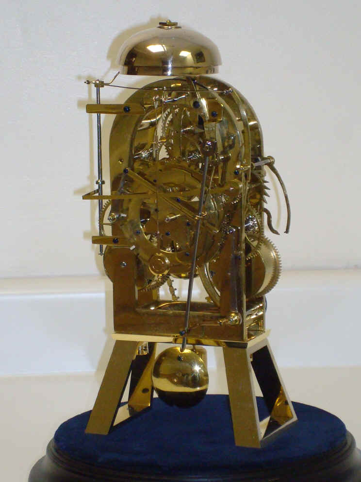
Maker, Unknown, probably France or Belgium. c. 1820. Movement 10"h x 5"w x 3.75"d. / 13.5"h x 8" diameter over dome. Robert Robin endless loop type remontoire; 3.75 minute cycle 1. Tic-tac (recoil) escapement 0.6 second period pendulum, silk suspension. Two train, compound count wheel quarter strike on two bells using one vertically articulated hammer, strike train speed mediated by a pendulum rather than conventional fly fan, but a conventional fly is used to mediate the remontoire rewind cycle. Strike control uses 'kick-starting' method. Instead of the use of clock hands, the dial rotates counterclockwise against a fixed pointer.
Click on pictures for more detail.

robin_rem_mov.MPG robin_rem_mov2.MPG robin_rem_mov3.MPG robin_rem_mov1.MPG
A most unusual combination of features are demonstrated in this unique exhibition piece. It appears the maker was intent upon demonstrating an unconventional approach for many aspects of this clock. Most of the wheels in the movement are wafer-thin at less than 1/32" thick. High quality fit and finish throughout with all removable pieces having positioning pins; all screws highly finished and blued.
Unusual design features of the strike train: The first is the use of a pendulum to mediate the speed of the strike train rather than a conventional fly fan. The larger pendulum suspended by a knife edge performs this by connection to a toothed wheel looking very much like a conventional anchor escapement. It is reminiscent of early medieval clocks where the bell clapper was driven by a crown wheel that was similar to the crown wheel used in the clock's escapement. Here, instead of the clapper being driven, the pendulum is attached to a series of linkages that drive the bell hammer. Second the use of a double i.e compound set of count wheels. This allows the clock to perform the function of a quarter striking clock that would normally need two strike trains, to perform this function with only one. The bottom (higher toned) bell is stuck the appropriate number of blows, 1 through 3 for the first three quarters. The larger diameter (outer) count wheel performs this function. On the fourth quarter the hammer is moved upward to ring the top (lower toned) bell the correct number of blows 1 through 12 to indicate the hour. The inner count wheel, works both as a cam to lift the hammer to the upper bell as well as direct the number of hours to be struck. The entire count wheel assembly rotates once in a 12 hour period requiring the quarter hour count wheel to have twelve sequences of one through three quarter blows. These sequences are placed in ever longer spaces from each other to correspond to the hour count wheels one through twelve strike cycle. Third, there is no conventional 'warning' system to set the strike train. A cantilevered weight is dropped and a pivoted lever strikes over a pin, releasing the strike sequence. This method known 'kick-starting' using a 'flirt' which was used as a way to release the strike train on the earliest tower and domestic clocks. This is not very precise, but it is unnecessary as there is no minute hand!
The pendulum is at rest when locked to the left. A cantilevered, weighted lever is raised each quarter by a 4 pinned wheel rotating once per hour. When the lever slips off the pin, a small, movable arm mounted to the lever, the 'flirt', strikes a pin attached to a lever that releases both the pendulum lock and moves the countwheel detent out of the wheel's slot. A second hooked lever catches the countwheel lever keeping it on the unlocked position. The pendulum begins to swing to the right. A second type of 'escapement' acts on the same toothed wheel driving the strike pendulum to release the hooked lever allowing the countwheel detent to ride upon the rim of the wheel and lock upon it's reaching the end of the number of strikes needed. This arrangement is needed to keep the countwheel lever away from the rotating count wheel through the first full swing of the pendulum to prevent it from tripping up the countwheel before it has had time to rotate enough to clear the count wheel slot. (This function in a regular countwheel system employing a conventional 'warning system' would have been accomplished with a cam). The pendulum swings back and forth driven by the toothed wheel in the strike train as the count wheel detent rides along the rim of the wheel, allowing one ring for each full period. At the end of the sequence, the strike detent drops into the count wheel slot and shifting the small lever to catch the pendulum at just the time that it is near it's full swing to the left so the pendulum is held fast in the leftward position until it is ready for release upon the next quarter. A most unusual and, unfortunately, cantankerous system to keep in proper running order!
Now for the anomalies in the design of the time train: First the train is driven by a Robert Robin style remontoire. However, it is driving a wheel two wheels down from the escape wheel. Normally a train remontoire drives the next wheel down from the escape wheel. It's purpose is to isolate the escape wheel from the rest of the train, so including an additional wheel is inadvisable. (for more discussion on remontoire click here). Since the remontoire is operating further from the escape wheel than normal, it's period is quite long at 3.75 minutes per cycle. The other problem with this design is that the remontoire weight must be larger to overcome the mechanical disadvantage of being lower down the train. Remontoire are used in applications where accuracy is at a premium. This is contradicted by the rest of the clock's design. The escapement is a short anchor (recoil) which only spans four teeth with short pendulum; a fairly inaccurate system. More significantly, the time is read from a fixed pointer against a small 12 hour rotating dial. There is no possibility of accuracy better than a five minutes using this dial system. So what's the point of the remontoire if not simply for show?
Clearly the maker of this movement intended to convey several unusual ways to accomplish conventional tasks. It is most likely an experimental one-off movement.
Provenance: Christie's, London, UK, July 1, 2005; Lot #50.
1. The Robin remontoire was an invention of Robert Robin, France. In 1772 he presented a paper to the Academie Royale de Sciences on his remontoire for which he is best known. It is based upon the Christiaan Huygens endless rope system invented by Huygens in 1658 as means for maintaining power to a clock mechanism while it is being wound (maintaining power system). Robin's genius was to make this endless rope maintaining power system automatic through one of the wheels in the Huygens system being powered by the main going barrel and released periodically by a detent connected to the Huygens remontoire weight. This relatively simple, reliable system allowed a clock to have the portability of a spring-driven clock with the constant power of a weight driven clock. It also serves the same purpose as any other train remontoire of isolating the escapement from the inaccuracies found through the rest of the clock train
![]()
![]()
![]()