|
POUVILLON RESTORATION PROJECT - August 2011 Reassemble main movement all components between main frames.
Pouvillon-18-000.mp3.
Photo 18 001.
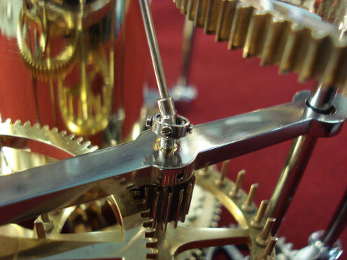
We have the universal assembly for the center seconds drive.
Photo 18 002. Another view of
the components for the little universal joint. The fourth screw, the lower
screw, is a replacement and they are too long and the head is too thick,
this is to be rectified.
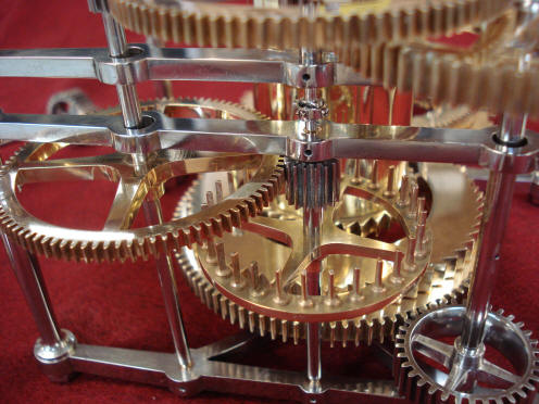
Photo 18 004
is the beginning or the first stage assembly of the main movement.
Photo 18 005 is another view of
the first stage assembly.
Pouvillon-18-005.mp3.
Photo
18 006, is the
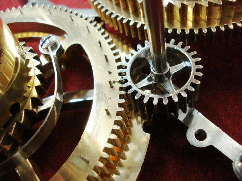
assembled universal joint. We can see the pin wheel, or the escape wheel
just below the plate and obviously the pinion.
Photo 18 010. Another view of
the assembled universal joint. As you can see we have the next frame
assembly placed above it. And the upper pivots, the upper arbors are all
loose as you can see they are all off center in the frame clearance holes.
Photo 18 013. Just another view
from the bottom of the clock.
Photo 18 014. The point of this
picture is to show the aligning center punch marks or countersinks where the
large four spoke pinion is meshing with the count wheel. This follows right
through the strike train and makes setting up this strike train extremely
easy. Because once you assemble the frames and everything is in place, the
strike is totally synchronized.
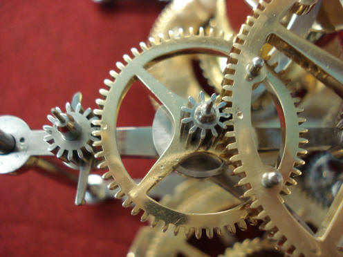
Photo 18 015. In the hub of this gear we can see right on the left hand
side the nut that holds it to its arbor and below it in the shadow we have
the pinion. You can see Mr. Pouvillon cut away the intersection between the
two spokes to expose the locating or the matching center hole or punch hole
in the corresponding tooth in the pinion that matches with the center punch
mark in the rim of the brass gear.
Photo 18 016. Here we have the next two sets of gears in the strike train. Again you can see each pinion and gear has a matching center punch which phases the whole train correctly. Photo 18 017 is a photograph to show porosity in the casting used to make the gear. Also of note in this picture is, what I would call, bad rounding of the ends of the teeth due to some previous restorer or possibly Mr. Pouvillon, excessively polishing these parts. Photo 18 018. Another picture to show the porosity in the casting.
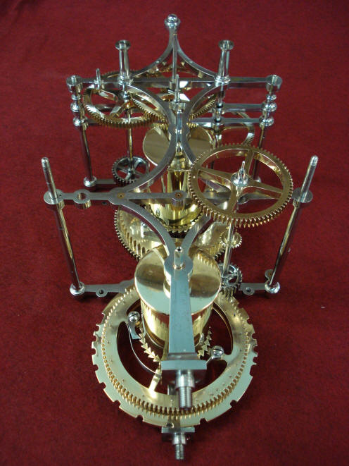
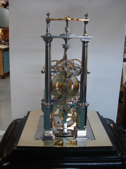
Photo 18 019
is the complete time and strike train assembled in their frames.
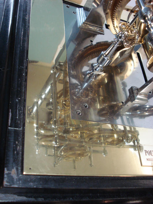
The rest of the photos
are just general pictures of the complete movement mounted back on its base.
It’s interesting to note the reflections in the base plate and also the
brass surround. Sometimes as you walk around the movement now, one has the
effect of this whole assembly floating on the surface of the base.
|