|
Orrery, begin inner planets gearbox - December 2018 This month we begin the inner planets gearbox component for the orrery. The inner planets gearbox is the last mechanical system to complete the orrery and by extension the last to complete the project. The inner planets gearbox components consist of Mercury, Venus, Earth/Moon system and Mars. The Sun is also a part of this and will also have a rotational period. This component presents challenges from the many wheels that must be sandwiched into a small vertical space. Throughout this component the vertical height will be the critical constraint.
The first component to be made will be the center concentric tubes upon which the planets and their gear drives will be mounted. There will be five of these plus a center shaft to rotate the sun. Since vertical height is a critical constraint, the first components to be addressed are the tube guide bearings. The first illustration shows what the overall height of the stacked bearings for the central inner planetary gearbox would have to be using a set of standard bearings out of the box and before custom machining by Buchanan. The height is 37 mm. There are five tubes with each needing a pair of bearings, one at each end. This allows for very close tolerances between the tubes, yet ensures a perfectly parallel space between them. The design will retain its integrity over time, whereas in antique orrery designs, the concentric tubes will, over time, begin to sag and touch each other resulting the need for greater power to overcome frictional loss. After machining the bearings are narrowed to a mere 23.2 mm for a stack of twelve; a 37.3% reduction in the height. The second photo shows the six different sized bearings needed; the outer rims have been milled to the new, thinner dimension with the inner rims yet to be done to show the contrast. Of course careful research is needed to ensure such alterations to critical parts can be safely made.
The twelve tube guide
bearings are shown in the context of the central gearbox.
A cutout of the inner
planet gearbox illustration is displayed to the correct scale and placed
within the completed section of the orrery to check for proportion, height
and clearances.
Here is a brief description of how I have to treat each set of 4 gears in
the
Buchananizing process.
Photo 905 (2nd photo).
I then check all my clearances. Height as well as other arbours. Can
the gears fit around the bearings in the centre of the gearbox? Is there space
for collets screws? Is it practical to make?
Photo 035 (3rd photo):
I then adjust the final tooth size so that the two small gears have the same
arbour position.
I have done this for 8 sets of four gears in this gear box. A few times
there have been knock on effects and I have to go back a few gear groups and
re adjust them. It is a laborious process. Then I update the excel
spread sheet. I also managed to shut down the drawing once and lost two
stages because they were not saved!
If you compare the first excel spread sheet to the one I sent today you can
see how much we differ from Hahn.
I can now move the gear sets around the centre arbour to get a good visual
balance.
Above is the first attempt (1st
illustration). Too much weight on the right.
I swapped the yellow and the red wheels and moved the small brown wheels at
the bottom to the left and this is about the best I can manage
(2nd illustration).
I
write:
This is very illuminating. When you have finished, you mention being able to
move the wheels around the center arbor to get a good visual balance. Is
this the final design? If not what is the actual balance on a drawing? When
you say you check clearances and mention height, how is this done, can’t be
from the drawings shown? So do you go back to the hardcopy drawing of the
side elevation, or is this what also happens on the E–drawing? Buchanan replies:
I refer to the e-drawing top and side view, the main orrery drawing and the
Hahn schematic continuously. A continual cross referencing takes place all
the time. It feels rather like playing a serious game of chess where you are
not allowed to lose. I would say it is heading toward the final design. I
have realised that I have not included the final 4 gears that drive
Jupiter’s arm. I am not worried as there is plenty of space for this. I am
also thinking of the frame design while positioning the gears. The e-drawing
is constantly enlarged and moved around when I am working on it. I have not
done a complete drawing of the orrery. It develops as I go along. I hope I
have answered all the questions.
This gives the reader an idea of the complexities involved in the approach
Buchanan takes to the creation of components in this project. This goes way
beyond simply making a set of wheels to get the job done, even in a set of
fancy frames. Much thought and design time is needed to achieve the correct
visual as well as mechanical blending to create mechanical art.
Gear table for the central planets gearbox, with comparison between Buchanan's and Hahn's specifications. The total tooth count in Hahn's design was 2028 and Buchanan's is 4135, more than twice the number. This is from the use of large diameter, decorative wheels in place of conventional, small in-line idler wheel sets. Table has been pixilated to protect proprietary data.
Buchanan writes: Here are the centre frames. Too thick right now. There will be gear rims 5/8 of an inch outside the frames. And the frames will almost disappear finally. The discs are 4 inches in diameter, I will start on the centre tube assembly first.
The first drawing shows the outermost concentric tube for Mars. Notice the way the tube makes a right-angled covering around the ball bearing structure. This is the bearing pit. If one looks carefully it it can be seen that has subtle notching at the corners to accommodate the bearings above and below. Each ball bearing must be housed in an exterior brass shell-pit which is integral to the concentric tube for stabilization.
The second illustration shows the upper and lower ball bearing sets. The yellow outlines are the center planet gearbox frames. Between those frames is the drive wheel set; above the connection to each planet.
The first photo shows the modified compliment of ball bearings. Next photo the ball bearings and the five concentric tube set. There are only four planets in the central solar system, but this design has an additional tube for Earth's moon, making five.
These photos show the concentric tube assemblies (in the first photo one is missing). The second photo shows the tubes telescoped.
The concentric tube assembly is now complete. The threaded areas in the first photo are for the containment rings that will seal each ball bearing assembly (those are attached in the prior two photos). The next photo shows those rings which also double as the mounting platforms for the planets as well as geared wheels in three instances. The completed structure is now a ridged, long-lasting structure for the five concentric tubes of the inner planetary gearbox.
These two photos show a three quarter and side elevation of the concentric tube set within the rough plate assembly.
Here the construction is seen next to the drawing. An incredible amount of engineering design went into this component to eliminate the possibility of friction developing later on. It is the same methodology employed throughout the project since most of the systems we developed were designed for visual performance at the expense of what one would consider efficient engineering design. That is, to accomplish the goal with this simplest, most robust engineering concepts. Therefore, we have to make sure we have accounted for all of the additional problems associated with this approach. The entire machine must be "over-engineered" to get past the myriad problems that a complex mechanism brings to the table. Buchanan now turns to the wheel works of the center planets gearbox
Buchanan writes:
I have the 7 gears cut and two to thickness. Next is to mount them on the
tubes, I think I will have more than 6 spokes on some of the larger
wheels as they are so thin, (0.5 mm).
The first two gears are spoked and fitted but not screwed. The next two are
machined to thickness. We are pushing the boundaries with these gears. I
have made many larger gears and quite a few this thickness, but not this big
and this thin. These first two are of the smaller size, they get a lot
bigger.
Buchanan writes:
The largest diameter is 2.9 inches. I will be able to increase the thickness
on the two largest to at least 0.6 mm. The boundary that we are pushing is
the degree of wobble/slant that we can tolerate. If the wobble is 0.1 mm it
is 20% of the thickness. Add end shake and wobble on the mating gear and it
is a large %. Extra spokes and attention to clearances all help, especially
the fact that all the tubes run on ball bearings. I have increased the depth
if the rims a little as well. I think we are taking it to the limit but not
exceeding it. I have 4 wheels spoked and fitted, but no screws yet.
The concentric gear set is completed. Five of the seven
wheels shown here will be attached to the concentric tube set.
The wheel set is now
mounted to their planet tubes. Buchanan writes:
I have all the centre wheels properly mounted on their collets. Screw length
and screw head thickness is very important as we are working with 22 thou
thick gears and the thread is tapped into the gear so the screw cannot be too
short as we have strength issues and they cannot stick out as we have
clearance issues. The same with the screw heads.
The illustration above is the initial layout for the center planet gearbox to determine clearances.
These two photos show the build out of the gearbox superimposed on the layout drawing.
The illustration shows
the drive wheels from the center input arbour to the Jupiter arm and the
main gearbox. The blue circle is the present frame size. The
drawing is printed on paper to scale and inserted into the orrery to
check for fit. Here we see a potential problem with the outer gear of the
center planets gearbox touching the bezel of the now completed Jupiter
component. This method of checking for component conflicts with a paper
mockup inserted into the machine has been used many times in the past and
has saved unnecessary reworking of fabricated parts.
Buchanan writes:
I have finished cutting another 10 gears, which leaves us only 11 more to
cut to complete the clock!
I will now do a physical depthing measurement on each set and then plot out
the position of each pivot on a drawing. I will then be able to extract a
set of X Y coordinates to allow me to machine the pivot holes on the plates.
It looks like my lower plate will be too small for the outermost bearing but
it is no great deal to replace it now, it only has 5 plain round holes in
it. The.(second), photo show the depthing check
on the jig borer. Next week I start to mount the wheels between the plates.
I will have to work out the correct sequence to do that so I don’t build myself
into a corner.
Buchanan writes:
This is the final layout for the centre gearbox. I have positioned every
arbour accurately ready for planting.
Notice how Buchanan has been able to plant the wheels in a visually balanced
way around the center.
Buchanan
writes:
I have finished spoking and machining three more gears that are below the
centre gearbox. The large gear on the top is fixed to Jupiter’s arm and is
driven from the centre gearbox. The next two equal sized gears bring the
drive to the moons past the Jupiter arm drive gear. The centre of the outer
moon drive gear has to pass the teeth of the Jupiter arm drive gear. See
arrows in photo 739 (first photo). This dictates the diameter of the moon
drive gears. This pushes the outer teeth of the moon drive gear over the
orbit dial on Jupiter, second arrow. There is no problem, as you read the
dial on the other side where the pointer is and the gear only passes over
the orbit dial every 12 years.
Buchanan writes:
Today I made 4 bearing housings and a spare. I also made the collet that
holds the main lower plate to the centre shaft of the orrery. I bored out
the plates for the two bearings as well. I have all the pivots placed on the
lower frame.
Buchanan writes:
In the first photo with only two wheels I have a meshing/depthing problem.
I can fix this in two ways. Cut two very slightly smaller wheels or
move the outer bearing. (I cannot move the centre bearing as it is in the
centre!)
Before I do the easy thing, which is to cut a smaller wheel, I need to know
if this is the problem or if all the other meshing gears are also a problem.
The adjustment is only 5 or 6 thou. What I have been doing is to check each
set of gears affected for depthing. The problem is that there are 4 sets or
8 gears that could be affected as follows:
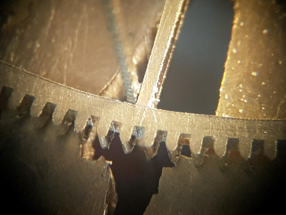
The trusty scroll saw Buchanan has used to cut all of the flat stock in this project. The binoculars are 10X magnification.
Notice how straight the cut is made even at magnification.
The corners are nearly perfect, something that cannot be achieved in a computer-controlled mill. All of the precision in the initial cutting dramatically reduces the time needed for final finishing and polishing of the wheel.
Many people have inquired in the past what type of equipment and blades Buchanan uses to cut the flat stock in this project. This clip shows that Buchanan is not only accurate but fast. It is a follow-on to a prior video done a while ago entitled "Making a screw in 60 seconds". In this video a complete pie shape is cut from a wheel. So with six spokes for a typical wheel, this comes out to about 21-25 minutes per wheel.
|


What a nice way to end 2018!
![]()
![]()
![]()