|
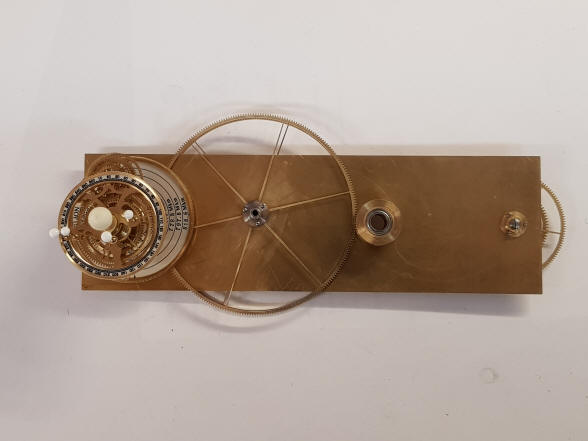
Orrery, Jupiter armature drive wheel set - November 2018
This photo shows the
beginnings of the armature for Jupiter.
Due to space
constraints Buchanan must check carefully the positions of Jupiter and
Saturn as they would pass each other in their closest and farthest positions
relative to each other due to their planetary tilts.
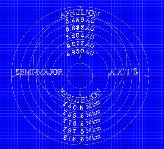
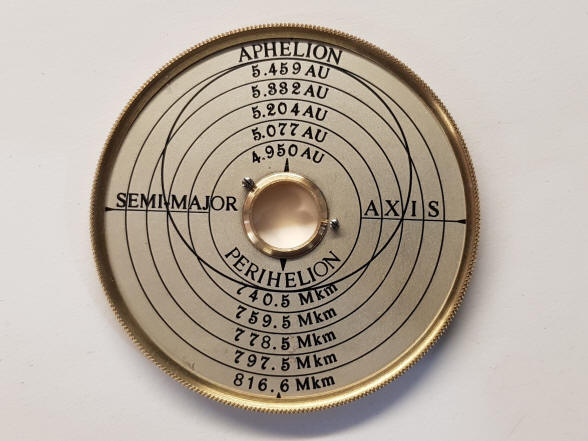
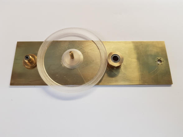
The first photo shows
the computer design image used for the engraving of the Jupiter’s orbit dial.
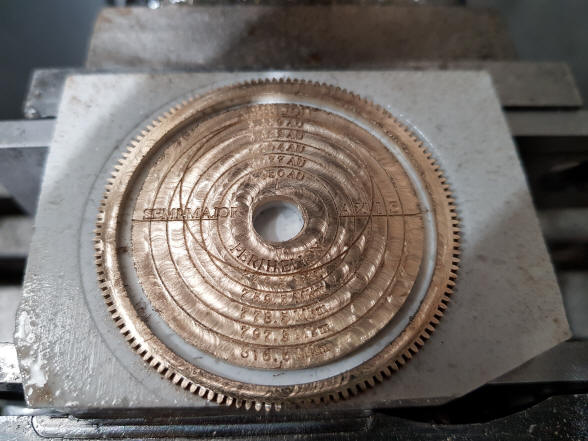
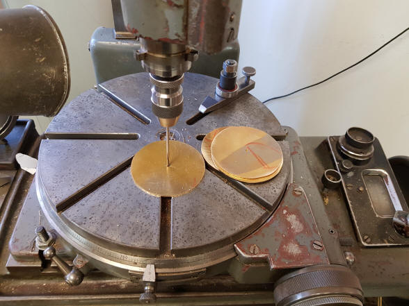
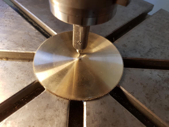
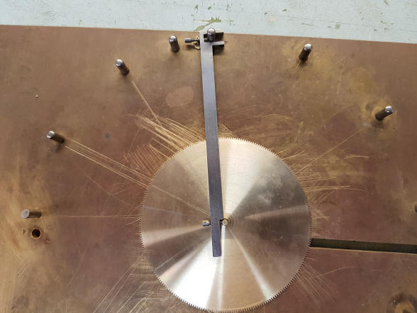
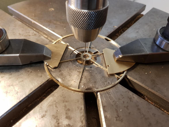
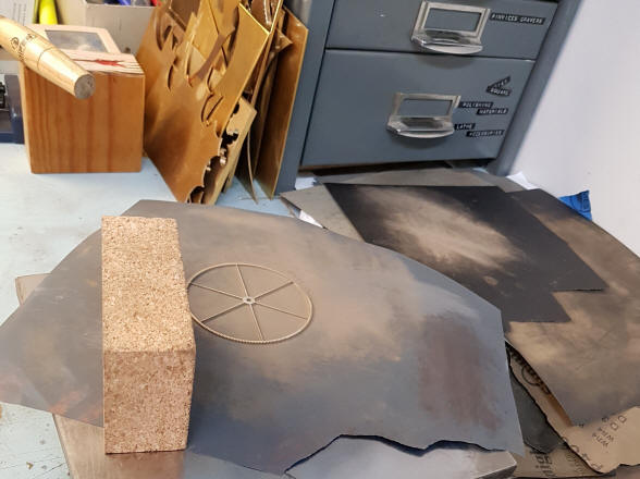
The next photo shows the beginning of the engraving process. Notice the
brass blank has teeth around the perimeter; it is a recycled wheel from a
prior project.
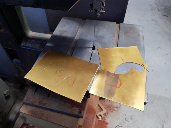
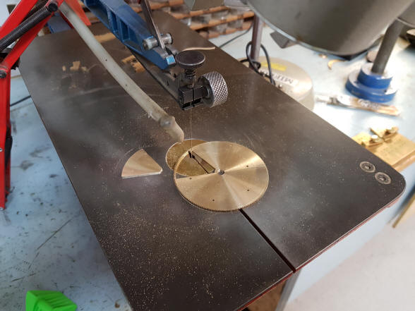
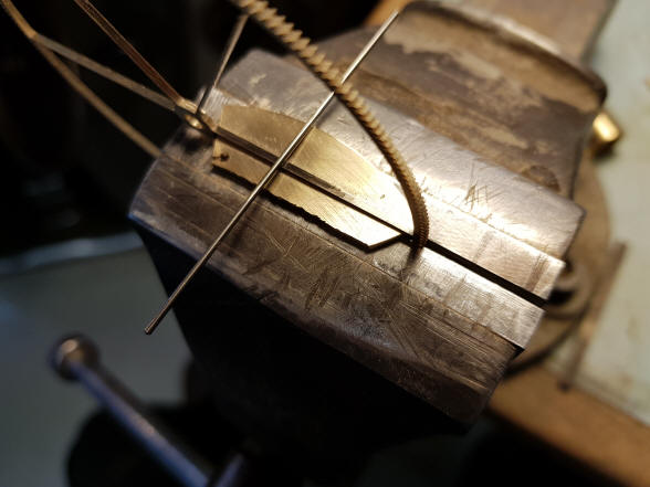
The toothed rim is cut
from the rough-engraved blank and in the second photo the surface has been
sanded smooth, revealing the dial engraving.
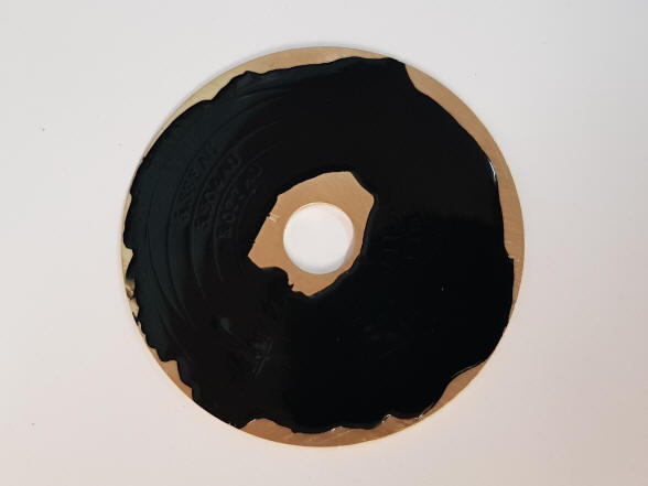
These photos show the
orbit and degree dials finished with black dial wax to fill the engraving
and the surfaces silvered. Then the dials are ‘dressed’ with their internal
and external bezels, the latter having a knurled edge.
The parts count for the
Jupiter gearbox assembly is 89 parts.
The Jupiter gearbox and its own little world of moons is finished.
Buchanan writes:
Jupiter is finished. On to the Jupiter arm. I will first get a rough arm
design, (I will reduce the Saturn arm design on the photo copier), then I
can fit in the largest possible size gears and then we can go on to the
final design once everything is on the arm. This arm has an extension out
the back that carries the Saturn arm drive gears so will be rather different
finally.
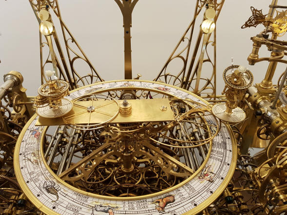
The Jupiter armature plate is mounted into the orrery to test for fit within the dial. From this angle the dial work of the tellurian and sun /moon complications on the right flow across the front, up and around to the rear of the machine.
Another view of the Jupiter armature plate.
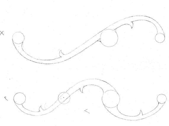
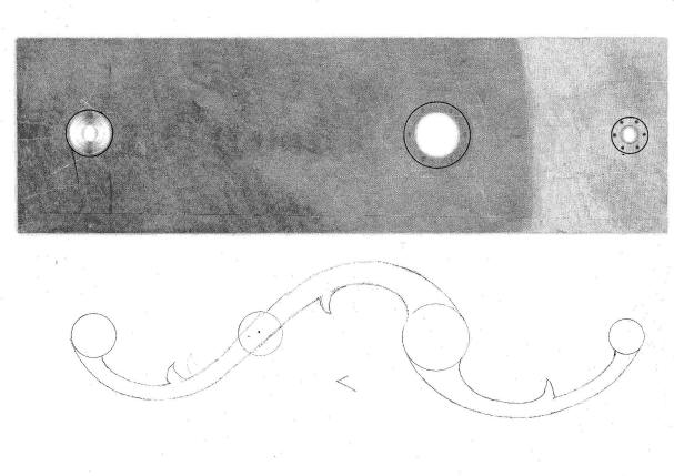
The
first illustration shows two options for the Jupiter armature; the lower one
was chosen. The next illustration shows the design under the actual armature
plate with the holes aligned.
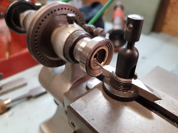
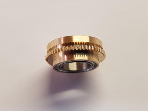
Buchanan writes:
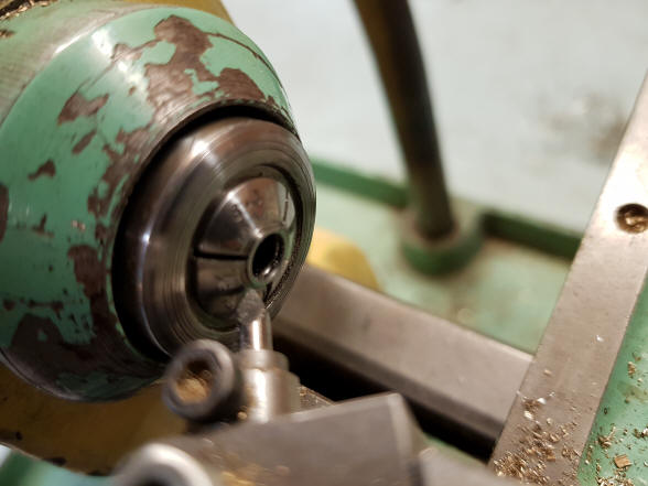
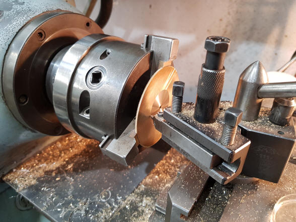
I have the centre drive gear mounted on to the bearing sleeve 934
(1st photo) in
machining the gear to fit the sleeve, 909
(2nd photo) is the
sleeve assembly, there is another input wheel to be added that brings the
drive from the centre gearbox. 248
(3rd
photo) is both gears mounted on the arm. 604
(4th photo) is a test
gear to check the tooth count and establish the depthing of the idler gear.
These four gears will have 252 teeth each. Just another 1004 teeth on the
clock.
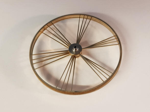
The four large idler
wheels, each having 252 teeth are now being cut from the brass sheet.
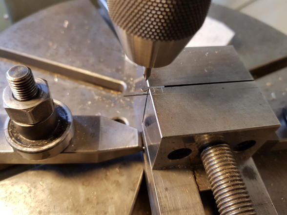
Buchanan writes:
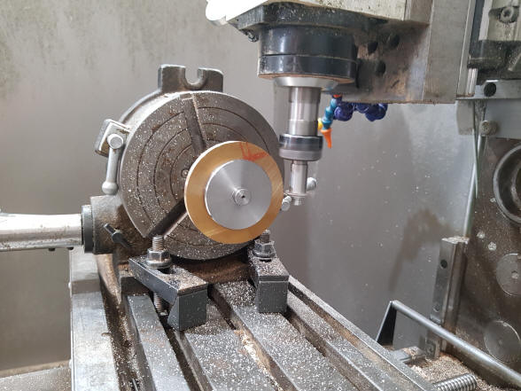
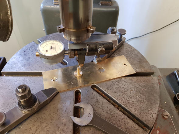
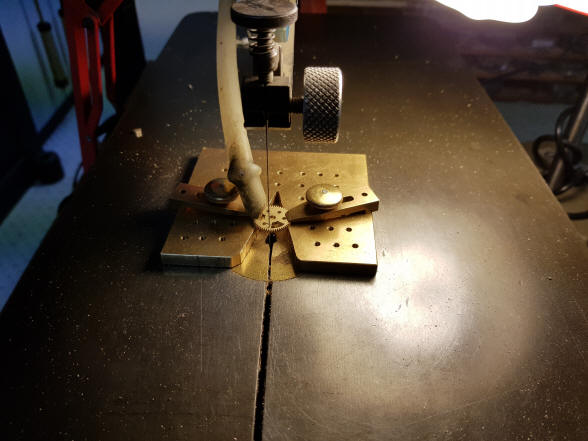
Here we are cutting the batch of four gears at one time as a stack of four
(1st photo). (2nd
photo) is the Jupiter arm mounted on the jig borer and centring on the
brass mushroom spigot, so that I can machine the arm for the gear bearings.
You can see the basic arm design scribed onto the brass plate so that I
could place the brass mushroom centre over the design.
Buchanan writes:
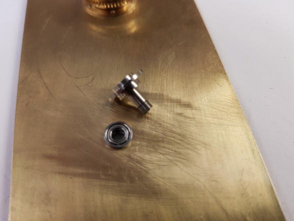
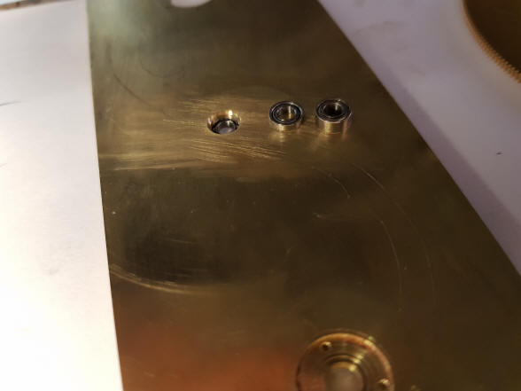
The bearings are fitted into the Jupiter arm
(1st photo). I had to
reduce the thickness of these two bearings due to space constraints
(2nd and 3rd
photos). I have also made the outer concentric arbour and am now
machining the 1.6 mm thick gears down to 1mm thick
(4th photo).
The second photo shows
Buchanan
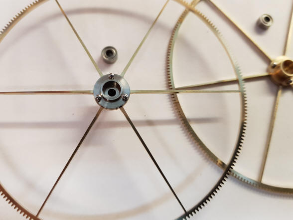
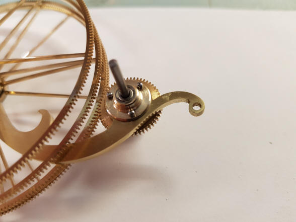
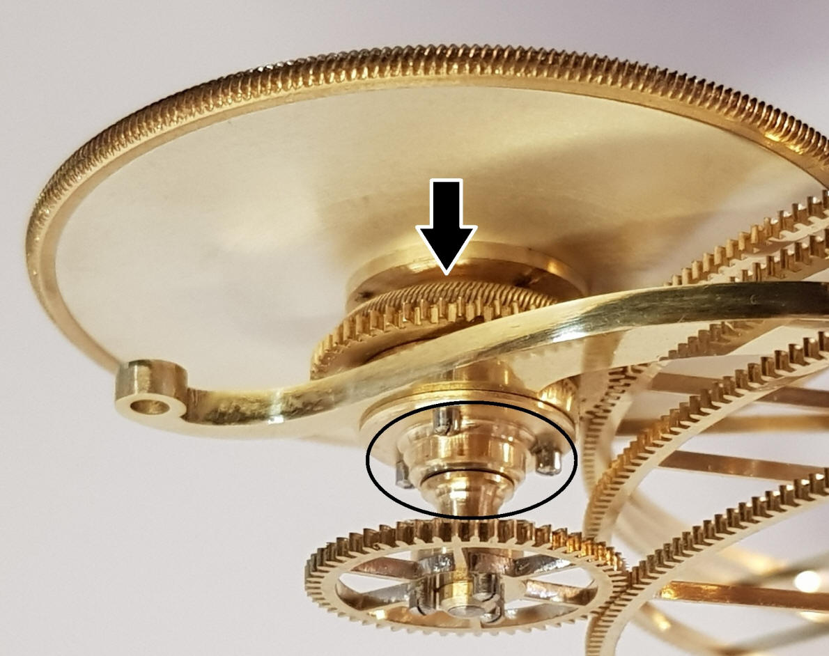
The
center hub is drilled and tapped, 1st photo, and the hub
attachment is then secured. The small ball bearing just above will fit into
the center recess area. There is an arbor that passes through the center to
carry the next set of wheels.
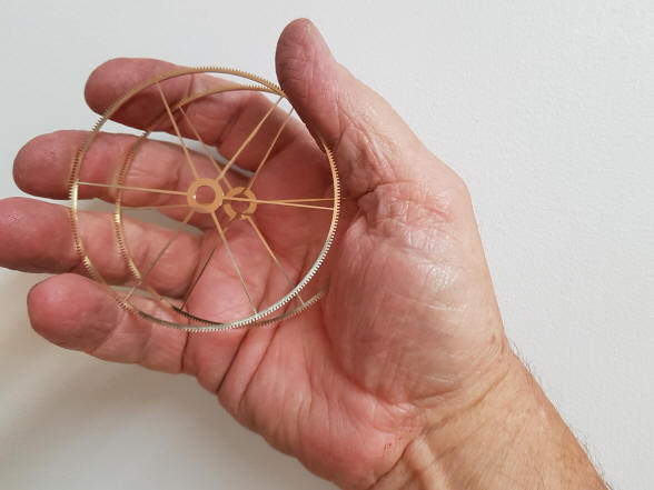
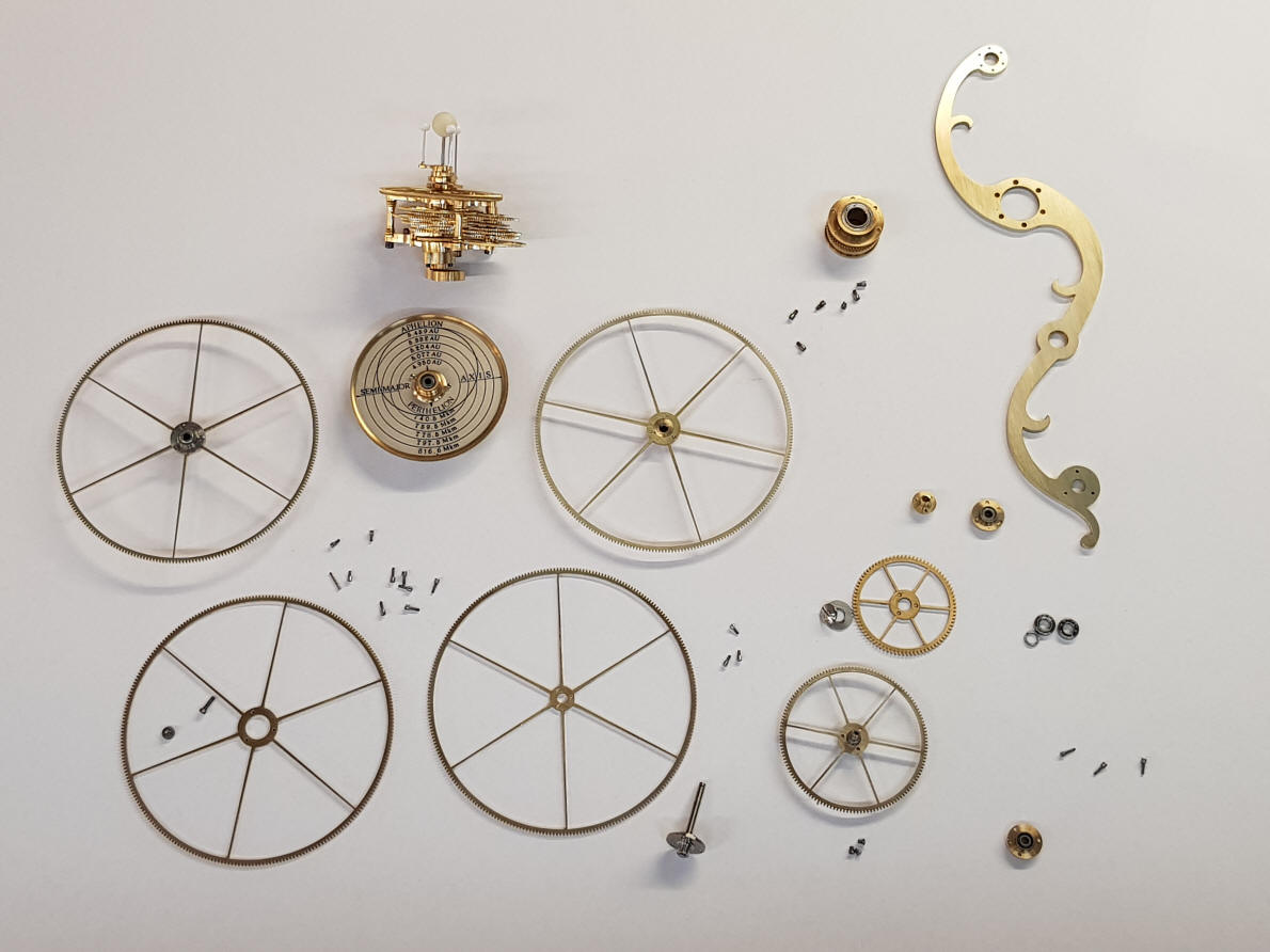
The wheel set, and
those wheels set into the blank armature plate, (photos 1 through 3). Photo
four shows that armature installed into the orrery with Saturn opposite.
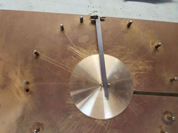
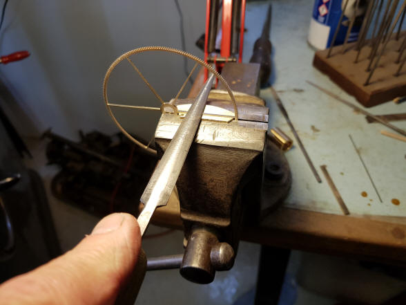
Buchanan writes:
(1st photo),
754 is burnishing a spoke with a hard polished rod. The rod is just rubbed
backward and forward along the length of the spoke and smooths the surface.
A lot of English clock makers finished their spokes like this in the old
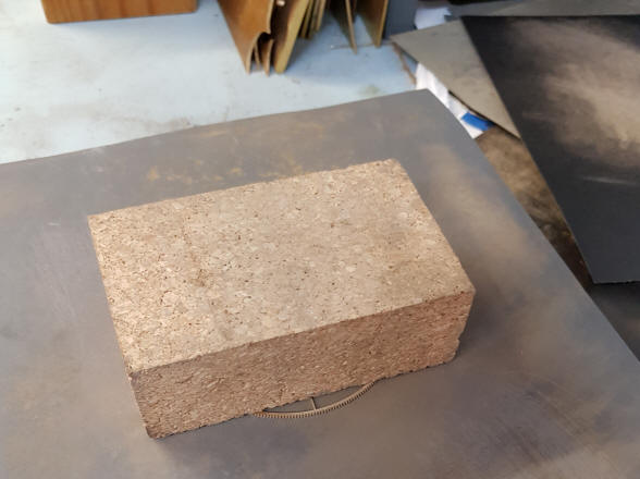
days. (2nd photo), 207
is the surface plate and cork block that I use to finish flat surfaces. And
115, (3rd photo) is
the gear under the block. Light pressure is needed or the part is pressed
into the sand paper and the surface becomes domed.
I did a quick calculation and there are 25 inches of scroll sawing on each
wheel, so, this batch of 4 wheels have 100 inches of polished edge! That is
100 inches of cutting 100 inches of rough filing 100 inches of fine filing
and 100 inches of burnishing. There are also 96 square corners to make sure
they are perfectly sharp and square with no saw or file marks. And I wonder
why my fingers are stiff at the end of the day.
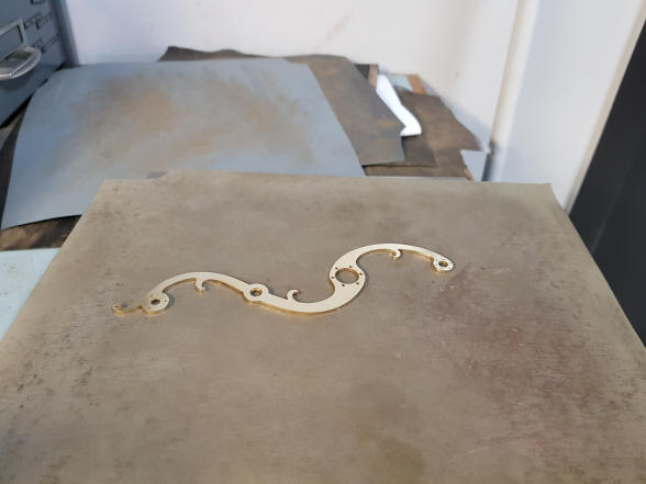
The Jupiter assembly before the armature plate is fretted into a curvilinear frame.
Buchanan writes:
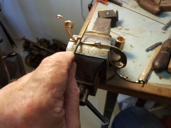
Today I semi-finished the Jupiter arm (made 2 more filing buttons),
(1st and 2nd
photos). Drilled and tapped the mounting screw hole for the pointer,
(3rd photo) and made
the bearing holder for the lower end of the input arbour
(4th and 5th
photo), then I spoked the input wheel and almost finished its collet
(6th photo).
If all proceeds well tomorrow I hope to have Jupiter completed as far as I
can at this point.
I am formulating a few ideas for the centre gearbox right now. I have an
embryo idea for the centre frames that could look very nice. It looks like I
could stretch the diameter of the centre box quite a lot and make it very
‘transparent’.
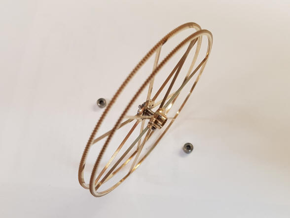
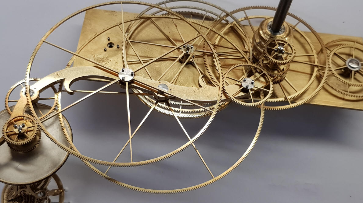
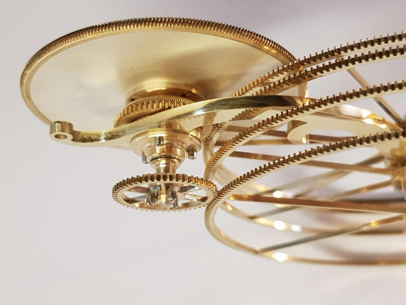
The first photo
illustrates the very thin wheelwork. The four large wheels are
only 1.0 mm thick and are stretching the mechanical strength of such large,
thin wheels to the limit; fortunately these are all very lightly loaded and
so will keep their integrity. This
design is necessary due to vertical dimensional constraints as a result of
the numerous stacking of wheels that had to be balanced between the
individual planetary gearboxes and the central orrery drive hub which has to
feed all of the four inner planets as well as the outer planets of Jupiter
and Saturn.
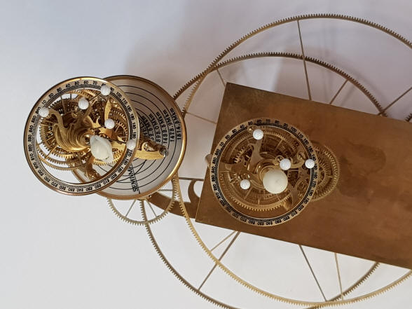
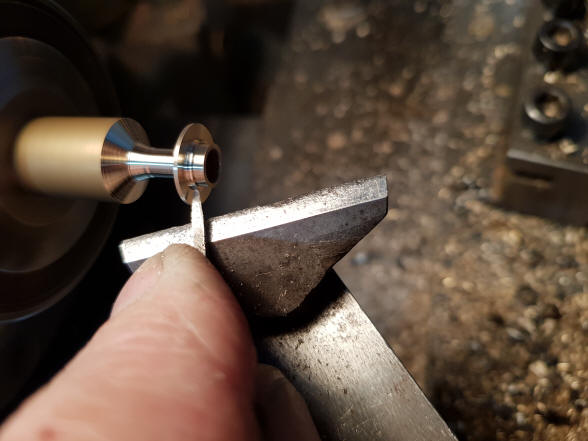
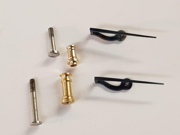
These
photos show the orbital dial hand and decorative turning of the tiny pillar
and screw holding that hand. The upper set for Jupiter, the lower belonging to
Saturn’s orbital dial.
An additional 60 parts within the drive armature added to the 89 contained within the Jupiter gearbox.
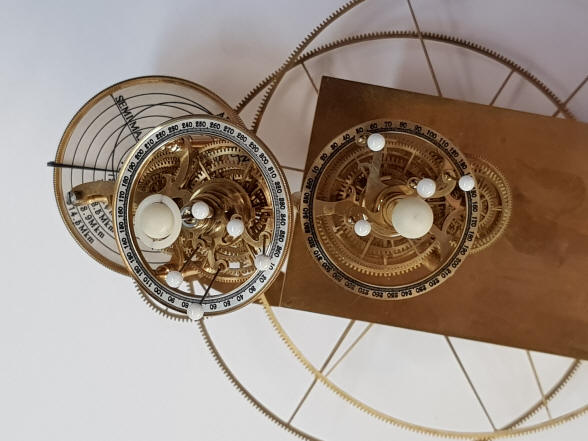
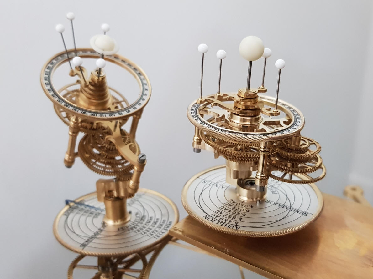
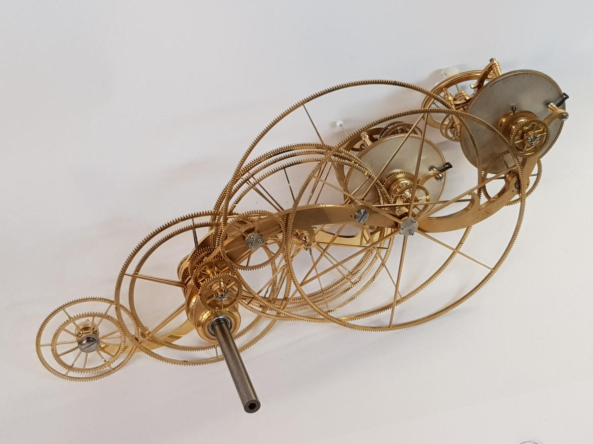
These two photos show
the completed underside of the Jupiter / Saturn assemblies; left with the
planets at their furthest point, and right their closet point to each other.
The large transfer wheels fulfill their function of filling in the empty
space between the planetary gearboxes.
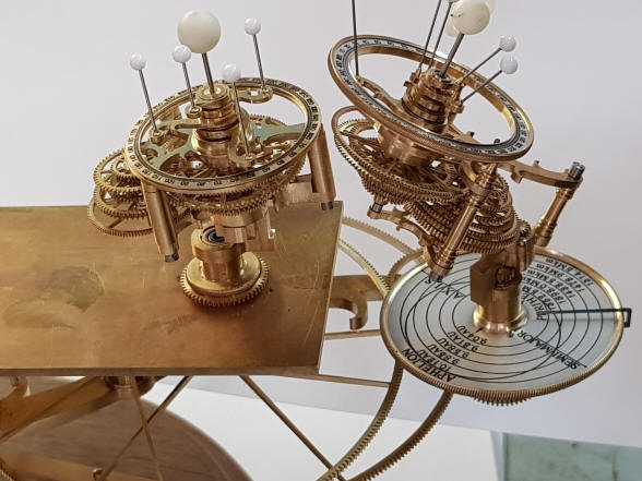
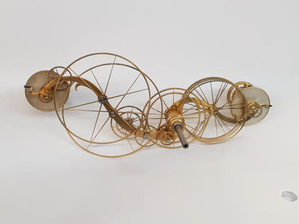
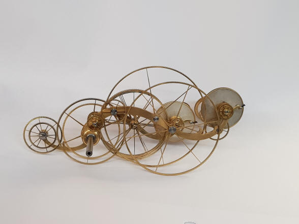
A rear, three-quarter
view of the Jupiter / Saturn assembly.
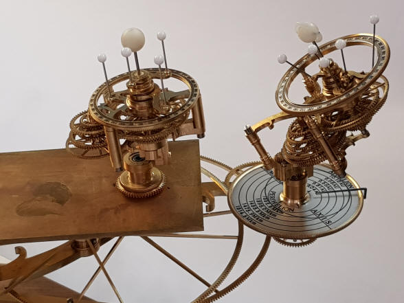
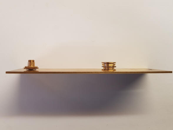
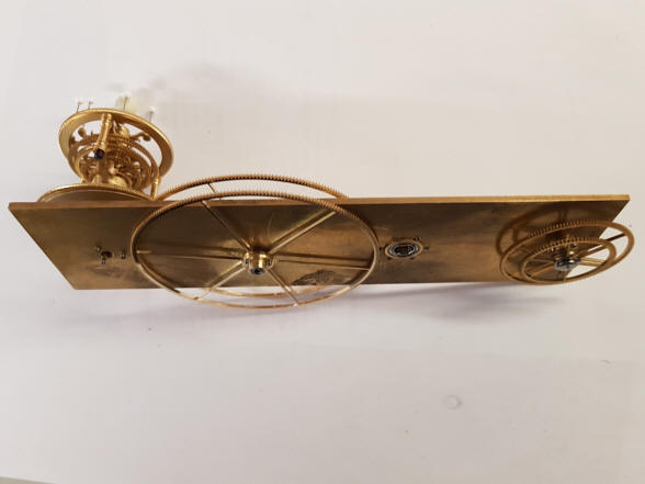
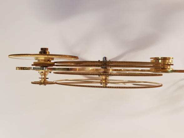
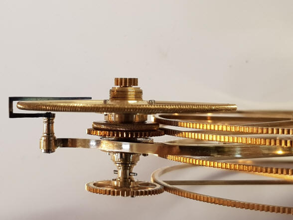
An edge-on view of the
Jupiter / Saturn assembly. The large transfer wheels from this angle seem to dwarf the
planetary gearboxes, yet fill the space between those and the central hub.
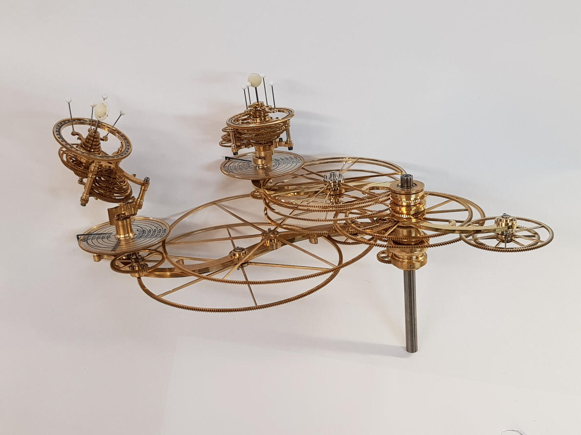
This photo nicely shows
how Buchanan has created both an airy yet substantial design; eliminating
the mundane conventional rectangular armatures to the outer planetary
gearboxes with elegant, inconspicuous and sinuous frames. The wheels fill in
the spaces between and prevent the two outer planets from looking like two
rotating islands within a largely empty space.
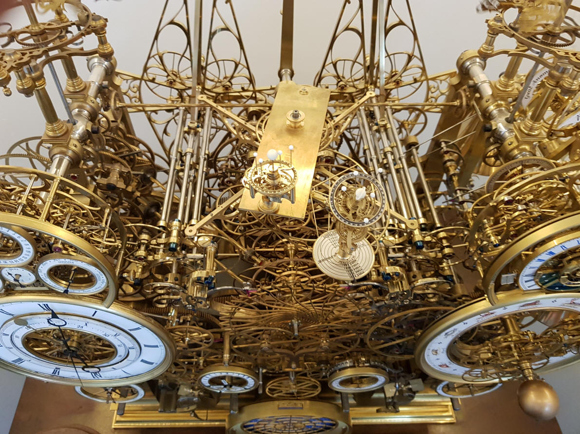
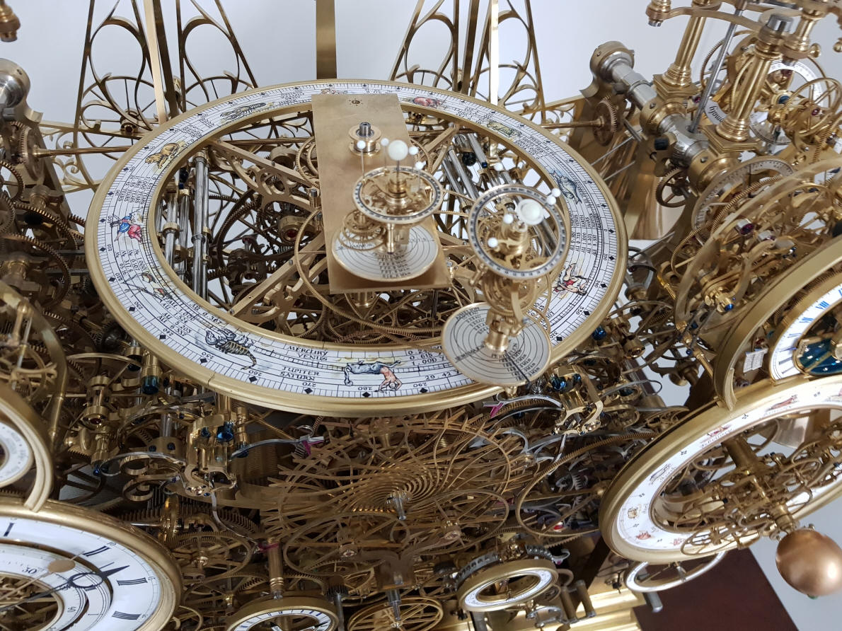
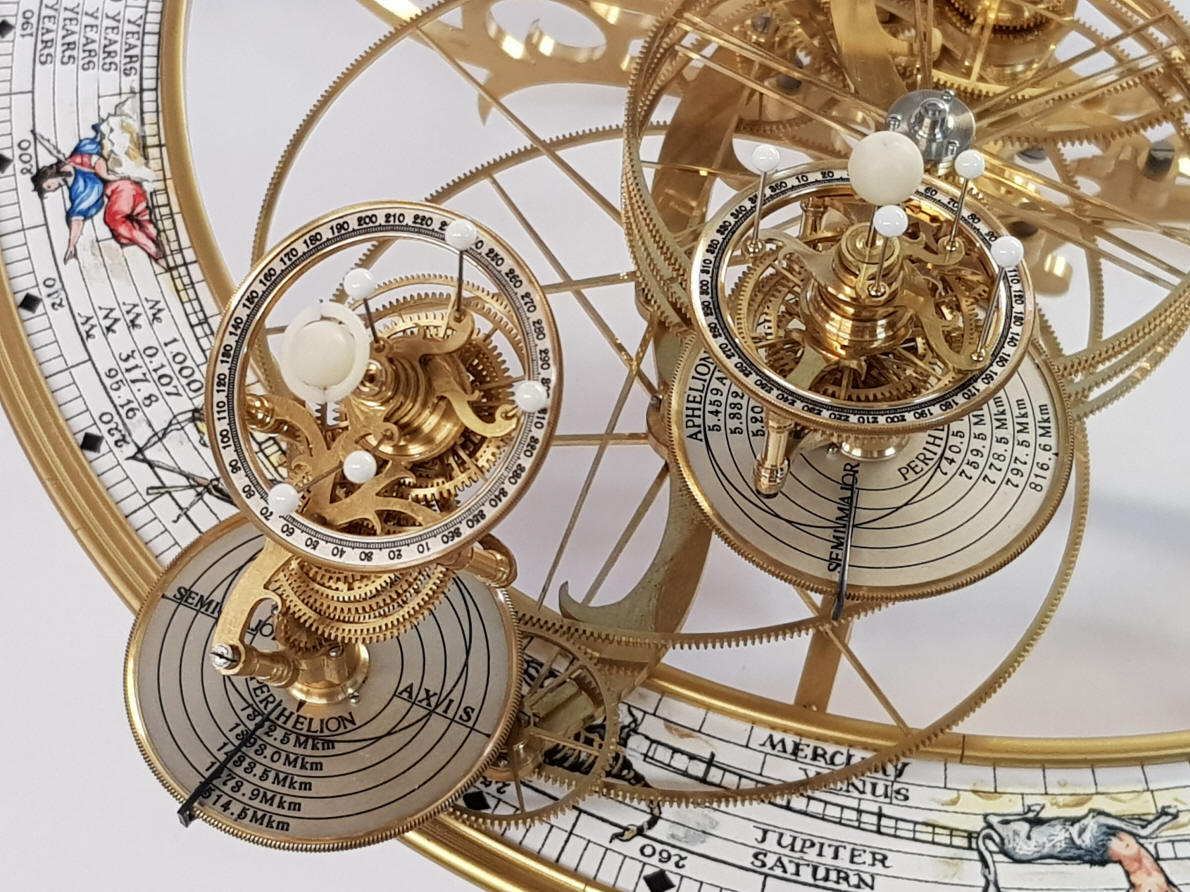
What can I say? The
planetary pair above the revised, more colorful orrery dial is perfect.
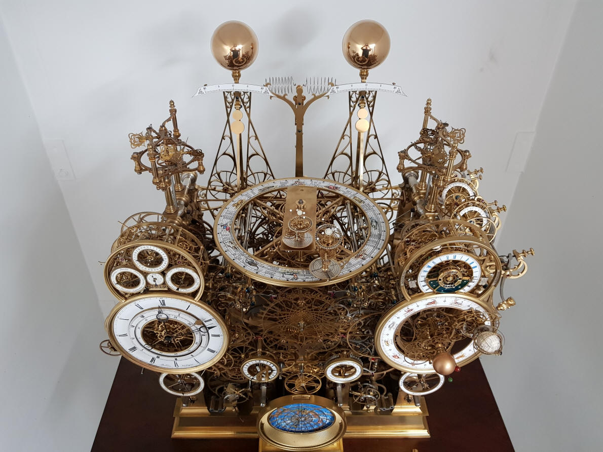
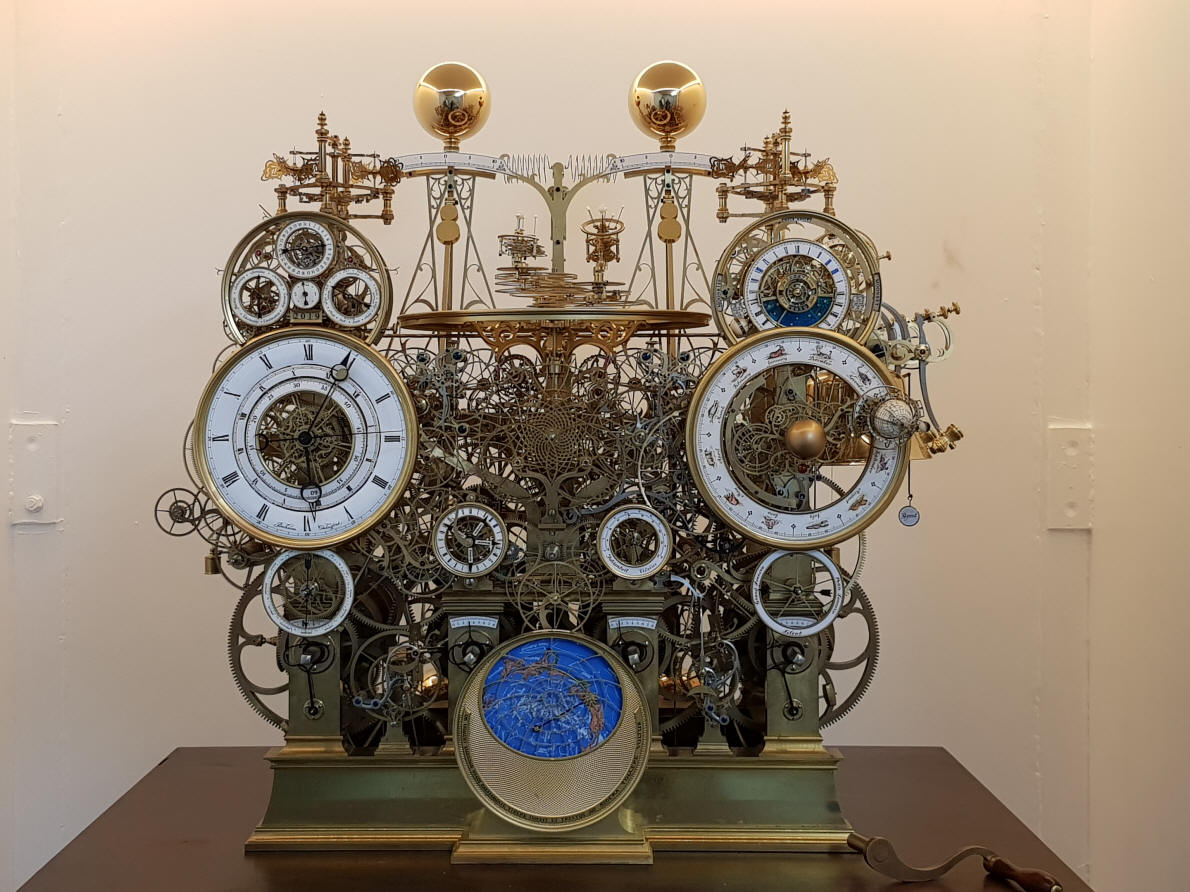
The front elevation
shows how the elements of the orrery are beginning to fill the last open
space left on the clock.
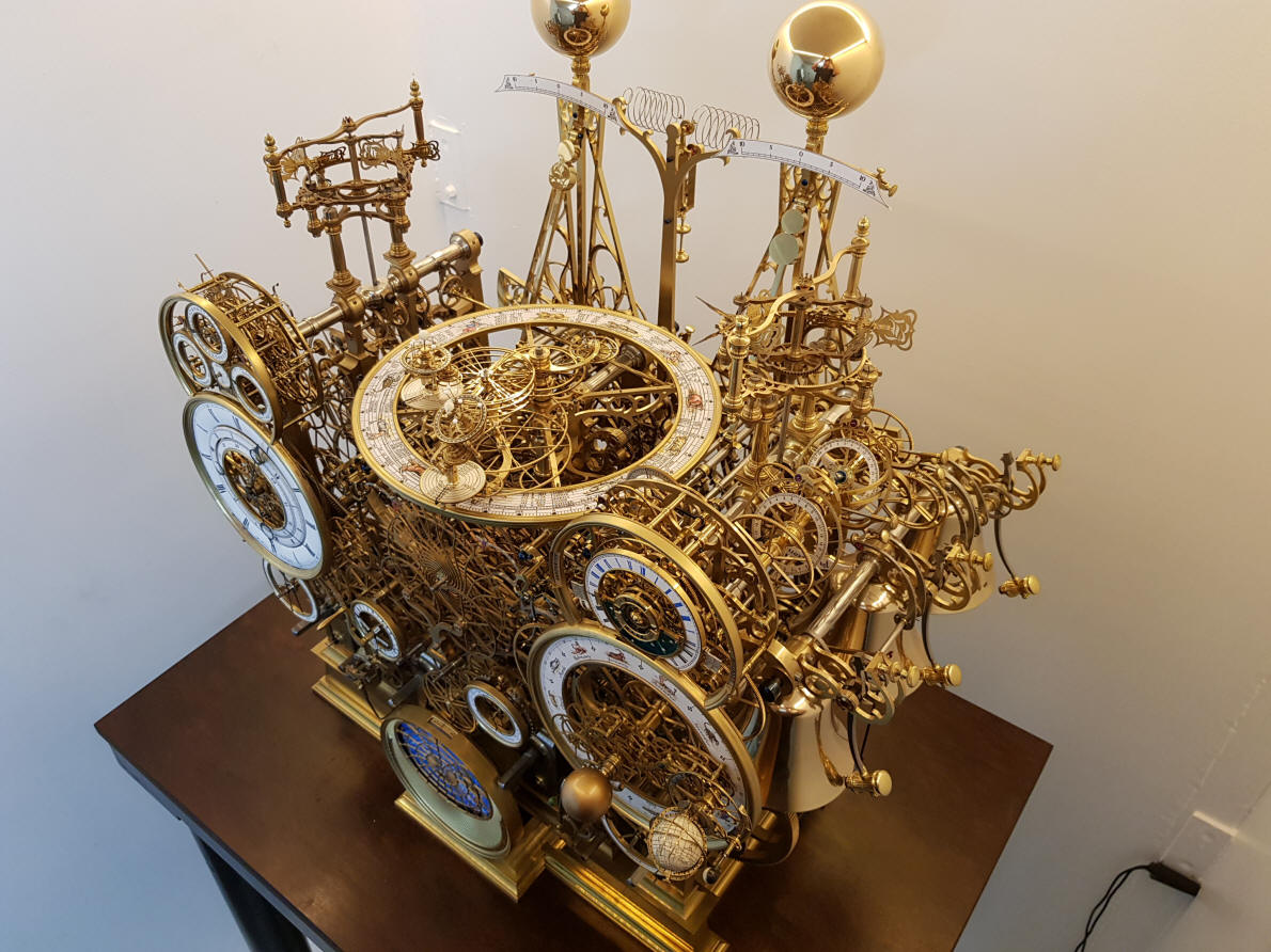
This three quarter view
reveals the immense complexity of the machine. The orrery seems to disappear
amongst the forest of wheels. |


![]()
![]()
![]()