Strike and repeat control assemblies, continue main strike fly detents - May 2011
This month we continue with the fabrication of the strike train systems. We now proceed with the main strike fly fan detents which were begun in February. Two are necessary, one for the quarter and one for the hour strike functions. These detents are directly attached to their respective racks and in conjunction with them allow the strike train to operate for the appropriate amount of time to count out the correct number of strikes on both the quarter and hour bells. Buchanan will continue with our convention of using a bird-like allegory for most functions requiring a pallet or stopping action.
The first photo shows the detent mockup completed last February in the upper left hand corner. One can see the bird caricature. We must include the same dimensional characteristics present in this mockup in the final part. The entire bird is mounted to an arbor that pivots within a blocky rectangular bracket. One can see more of the initial setup of this mockup on the movement in the February 2011 chapter. The final design must eliminate the bracket and have the bird pivot inconspicuously within the slot cut into either end of the horizontal plinth upon which they will be mounted. This is the large piece in the middle of the photo. First the raw stock is cut on the reciprocating hack saw, second photo, from stainless steel since the final finish will be a polished silver finish. All silver parts are made from this material. The two angle brackets are cut in the third photo and the arbor upon which the bracket will pivot is fitted in the last photo.
Last month I described a bit on how this arbor was attached, The two photos show this in more detail. This part must withstand the force of the main strike fly whip as it is stopped by the bird's beak to terminate the strike sequence. While the force is relatively low, this is a critical safety issue since failure of the detent would result in a strike train runaway. The end is therefore squared so as to be able to be tightened with a conventional clock key. The entire part is fully recessed within the plinth and so it would be difficult to get a good purchase on this part for the purpose of tightly securing it with conventional methods. A jeweled chaton will later cover this area shown in the second photo.
This photo shows one angle bracket in place. The associated strike train fly whip is visible just below the bracket corner. Those folks with wheel cutting experience can appreciate the several different wheel cutting techniques shown within the main fly fan assembly in the lower right hand corner. From front to rear: Conventional external rim cycloid teeth. Next, teeth cut on the interior of the wheel rim and finally an angled bevel toothed wheel.
These four photos show the various stages in the fabrication of the detents. In the second photo Buchanan uses the first completed bird beak as a template to hand file the second for a close match. The extensive hand working of parts throughout this machine will give it a quality of craftsmanship, what I call 'warmth' that is absent in a computer controlled manufacturing process.
The two bird detents are shown in their respective positions on the horizontal plinth. We were able to accomplish the attachment of the detents with minimal disruption to the decorative lines of the plinth. The detent arbor pivots are in a pair a jewel bearings. One is located with a blind hole, just beyond the outside front surface of the plinth, with the other located on the rear; out of sight.
Buchanan now turns to making two pillars that will hold the rack let-down flies. These flies mediate the speed at which the racks will drop. In conventional clock movements the racks simply fall under the influence of gravity or if positioned in a way that this is not possible, are pushed via a spring. In our movement the racks could fall simply by gravity, but they are rather large and the rack tail will contact a snail cam whose rim will be delicately skeletonized. So the prevent any damage, we will employ these flies to let the rack down at a controlled speed. Besides, two more fly fans will add to the visual fascination of the entire strike sequence, and in truth this is the driving reason. The first photo shows fabrication of the interior mounts to which the brass pillar uprights will be attached. Two of these mounts, one secured in place on the plinth surface, are in the next photo.
The first photo shows the mount next to the pillar with the next photo showing it tucked flush into the pillar's lower end. A rod, the length of the pillar with threads on each end will screw into the center mount hole and also be secured to the top end of the pillar. In this way we are able to attach the pillar to the plinth with no visible fastener points. We want the frame to look as if it were made from one milled piece and without the distraction of obvious fasteners. Theoretically it would be possible to create such a frame out of one piece, however that would make it impossible to assemble the myriad parts needed within the frame. We realize that such clever assembly techniques could pose a problem in the future for someone trying to take the movement apart for service. I will have these points printed out and hopefully this will be kept with the clock for any future repair person to consult.
The pillars are now shown in place. These will later be shaped into the same decorative format as the rest of the movement frame.
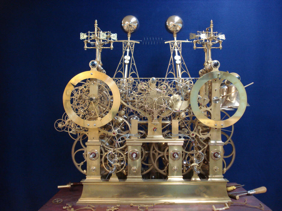
An overall view of the rack let down fly pillars and bird detents within the movement.
|