Strike and repeat control assemblies, complete initiators - April 2011
This month we continue with the fabrication of the strike and repeat control initiators. 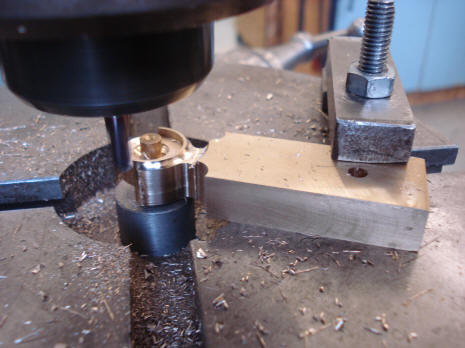
 

 The above photos show the fabrication of an additional drop down frame which will house the components of the strike and repeat initiator systems. Note that we keep our design consistent with that used for the time train remontoire fly fans.
The ratchet wheels are fitted to the initiator fly fans.
The mating ratchet pawl springs are fitted. We keep our design consistent in that we use oversized curvilinear springs for the ratchet pawls. It is the same design used in the remontoire fly fans as well as the main winding barrels. These springs are not only decorative in this form, but also, due to their geometry, offer a more consistent and gentle force on the ratchet pawl. Notice in the second photo we keep our bird's head design for the pawl. This part will later be blued. Also one can see a chaton with the red plastic 'jewel cap' removed revealing a ball bearing assembly.
Buchanan now begins the fabrication of a mount that will hold one of the leaf springs which will 'load' the initiator wheels. The first two photos show the part still attached to the rough block. Next the part is then sliced off with the slitting saw. The part is now mounted to its position on the drop down frame along with its spring. Note the two red jewel caps which cover similar ball bearing pivots shown four photos back. The next two photos show the overview of the assembly. A close up of the assembly.
Now begins fabrication of the quarter strike cam detent. This part is driven by the time train and will trip the quarter striking under normal operating conditions. It will trigger one of the two initiator wheels that will begin the proper sequence needed to drop the quarter rack into place. Note that Buchanan cuts this complex piece in one pass out of the solid blank; just as was done on the pendulum balance anti friction wheel cages. A steel rim is attached around the jeweled piece. In this way we obtain a more finished look.
The first photo shows the initial mount for the tellurium in the foreground with the initiator wheels in the background. Next the assembly mounted within the movement frames. Third photo shows the first, conventionally designed sector gear that will both load a leaf spring and in turn use the energy from that spring to spin the initiator wheel. The last photo shows the quarter strike cam in place.
Now begins the fabrication of the second sector gear which is involved with the repeat function. The initiator wheel in connection with this gear needs to turn in the opposite direction. We have a pair of wheels and drive sector gears that are related closely both physically and operationally, but need to be power the initiator wheels in opposite directions. Here is another example where the design and engineering expertise of the Buchanan firm shines. An obvious solution would be to insert a small gear between another conventional, externally toothed sector gear and the initiator wheel in order to obtain the needed counter rotation. We chose another way. Throughout this project we ask ourselves "How can we make this part in such way as to fascinate and engage the viewer?" In this way we create not just a complicated and interesting mechanism, but a coherent piece of horological art. Our solution is both elegant and simple in theory, but a bit more difficult in execution. A scenario encountered many times. The second sector will have its teeth cut internally on the inner rim rather than on the outside rim as was done on the first sector gear. The first photo shows the brass blank with the sector gear's internal space cut out. The space within the sector is too small for Buchanan to employ the same setup that was used to cut the internal teeth of the two time train remontoire fly fans. See the chapter for April 2008, as well as the video showing that procedure. Since the cutter cannot be mounted to a proper drive, Buchanan has clamped the cutter to a small tube vise, second photo. The third photo shows how this setup fits within the confined space of the sector's cutout. The vise is then mounted to a reciprocating head on the Bridgeport machine, last photo. Instead of the cutter spinning to create the sector gear teeth, a single tooth of the cutter is reciprocated to do the same job.
These two photos show the tooth cutting progress, note the cutting wheel at the top of the second photo.
The rough blank is fitted to the initiator assembly and when satisfactory the internal toothed sector gear is fretted out, but is not yet fine-finished.
The two sector gears are now shown fitted side by side with their mating wheels. A nice presentation.
The initiator springs, once fabricated must be heat treated to bring about the proper temper. These springs need to be quite strong (stiff) to do their job. The springs are packed into a copper tube along with charcoal. The tube helps to distribute the heat evenly and the charcoal keeps surface scaling of the metal to a minimum. The package is heated at 8100 Celsius (14900 F) for one hour. Afterward the tube is quenched in a can of oil (see video below). These will later be polished and blued. The quarter strike spring is shown below.
Buchanan now fits the rough outline of what will be the lever that will be used to depress the internally toothed sector gear. This is the repeat initiation function. The last photo shows this lever in place just behind the tellurium dial. (See video below to view this and the quarter strike initiators function).
The externally toothed sector gear is connected to the strike initiator wheel and is triggered by the quarter strike cam. This part is now fitted with a spring-loaded safety lever, first two photos. This is needed in the event that the quarter strike cam in turned backward as would be the case if the hands on the clock were pushed backward. The third photo shows the cam depressing the lever in the normal operation; the cam turning counterclockwise. The last photo shows the cam approaching in the opposite direction, clockwise. The lever is harmlessly lifted out of the way and when the cam's wheel passes, snaps back to its proper position. This is another example of our trying to make this clock as user-friendly as possible. On most clocks, particularly those with strike features, one would never turn the hands backwards, but we design for this event.
Buchanan now makes some of the flat jewelling needed in the strike lever work.
Pictured above are the pivot points for the main strike fly fan detents. These will lock and release the main fly fans by blocking and releasing the long fly whips. It required some clever engineering since I wanted to minimize the disruption to the previously milled cornices of the plinth in which these were to be mounted. This required the use of a blind hole just behind the front surface of the cornice, photos one, three and four. In order to minimize the alterations to the plinth, the strike detent has to be mounted in a slot cut into the end of the plinth (there is a pair of these detents, one at each end controlling the quarter and hour strike train fly fans). Since the detent arbor is mounted into a blind hole, and the detent must be held within a slotted area within the plinth’s end, the detent itself must be allowed to slip onto this arbor while this is pushed though the slot and then placed within the jeweled end stone mounted in the blind hole; the other end is secured by a jeweled chaton. Furthermore, this part performs a locking function that is subject to some force, so this piece must be firmly attached to the arbor. This is accomplished by having the detent screwed onto the arbor and tightened by a key that will fit into that arbor’s squared end, last photo. Furthermore a taper pin will lock this assembly in place. The detent itself will be in the form a bird in keeping with our design for these functions. One will not be able to see the threads once the detent is in place. Nor will one see the square head for the key until the exterior chaton is removed. So to minimize any confusion in future years should this part need disassembly, a small plate will be attached to the bottom of the plinth ledge and engraved with instructions indicating that the part is threaded and that removal of the taper pin is only the first step necessary to the detent’s removal
Astro_04-11_vid1 Astro_04-11_vid2 Astro_04-11_vid3 Astro_04-11_vid4 For those who cannot use the built-in viewer I have added the YouTube viewers below.
The first video shows the reciprocating arrangement used to cut the internal teeth in the confined space available within the sector gear. The second shows the heat treatment of the initiator springs.
First video demonstrates the manual repeat function of the initiator wheel. The second is the standard quarter strike initiation.
|


