Refinement of remontoire components. Seconds drive, begin celestial train - April 2009
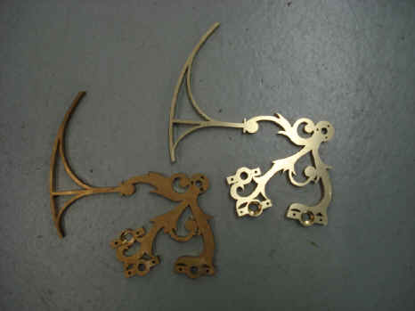
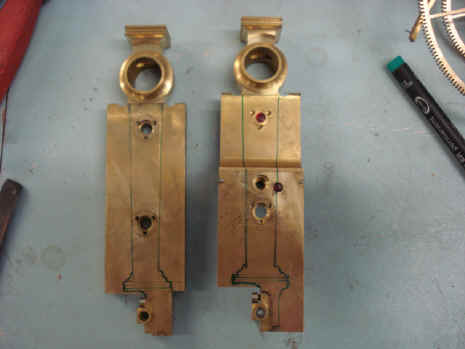
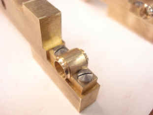
The remontoire cages were largely finished back in January 2008. However the pillars, poising weights and their support bars, as well as the remontoire support structures had yet to be refined and decorated. The final counter-sunk screw designs were chosen and the remontoire components were machined to accept them. In the two photos below the left component before countersunk drilling, the one on the right, after.
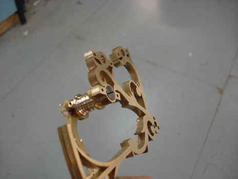
Here we see the row of countersunk screws. These are necessary in this assembly since the dual remontoire slide past each other with little clearance between them. The second photo shows the turned pillars which until now were plain cylindrical blanks.
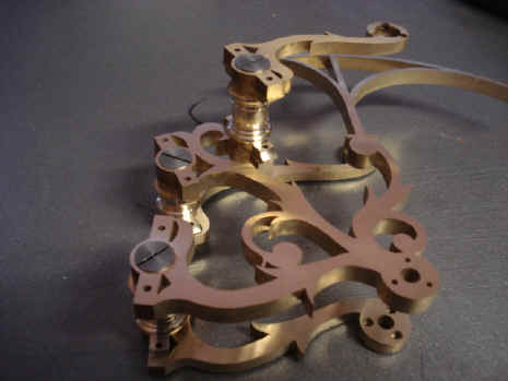
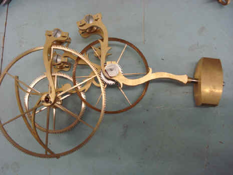
Below an overview of one of the two remontoire. Next the outline drawings of the remontoire support structures.
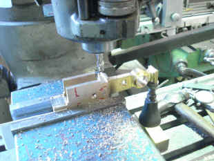
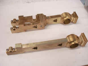
The support structures are milled out and the semi-finished articles at right.
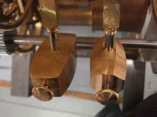
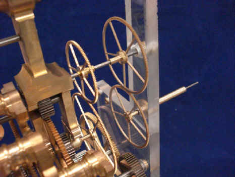
The remontoire poising weights are now milled to shape. This design is inspired by Jean Wagner as displayed in examples of his work in my collection. Next are shots of the seconds drive taken from the remontoire output.
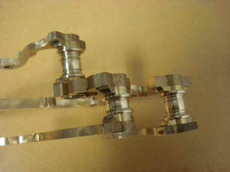
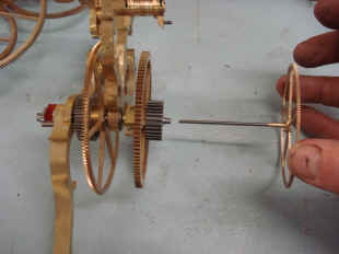
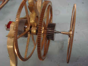
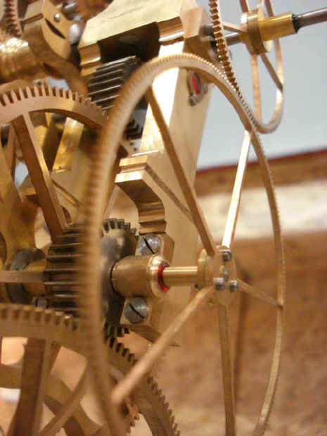
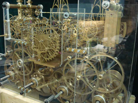
The seconds drive is delivered through a set of four wheels to get the correct ratios. These four relatively large wheels that are up front of the clock will move quite rapidly being one of many components to attract the attention of the viewer (see video clip below). Notice the use of jeweled chatons throughout this movement train.
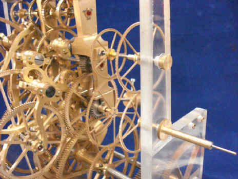
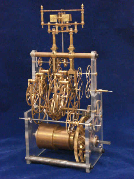
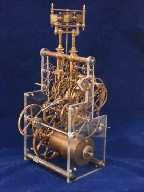
First photo is a close-up of the seconds output wheels against the remontoire support structure. The next few shots show the completed time train. It is one of the most complex I've seen for a single train coming in at 650 parts, 54 wheels. There will be another few added with the minute and hour motion works.
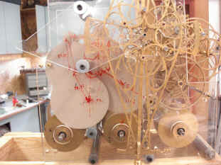
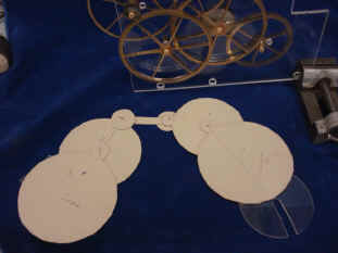
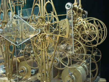
B. now begins the fabrication of the celestial train as it will be between the main movement plates. He first begins with a series of card board discs representing the desired wheel diameters to see if they can be planted where they need to be without spatial conflicts. Notice the mechanical and mathematical notations in red on the Plexiglas surface.
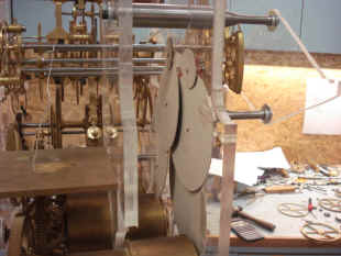
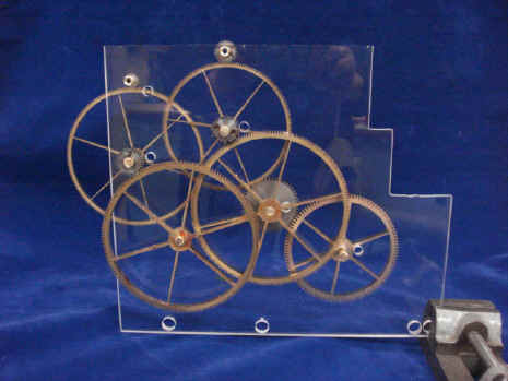
The wheels are now cut and planted on the Plexiglas plates. Next this is incorporated next to it's neighbor, the time train.
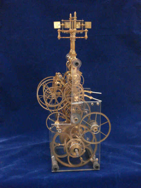
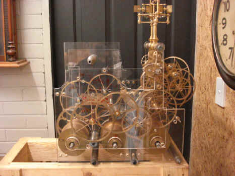
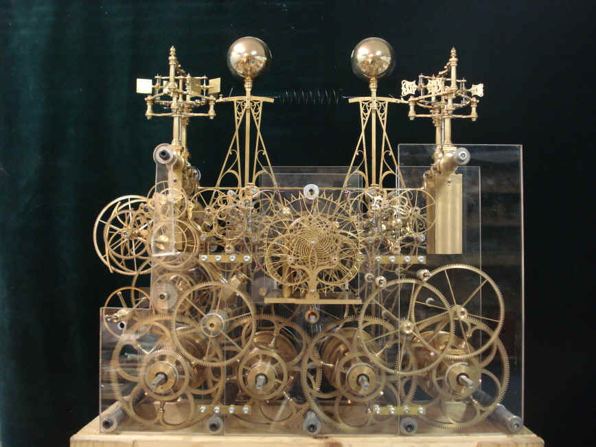
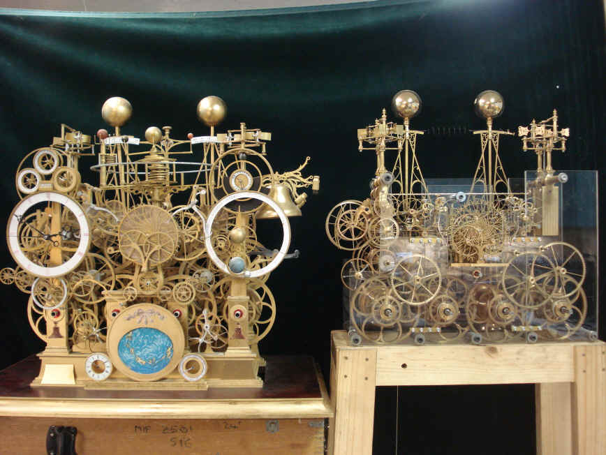
Here is the movement to date. The project is now about 30% finished. Another front and rear shot of progress to date.
The movement to date compared with the revised movement design mockup. While it may look like much more is finished than the estimated 30%, there is a myriad of work left. There is all of the behind-the-dial-work as well as the orrery and the two dozen complications. Then there is the polishing of all components, bluing of hundreds of screws and then plating. In the videos below B. has attached oversized dial hands to the seconds output. Another hand is attached to the time train clutch which rotates once per hour and in the rear is a small hand attached to the remontoire reload output. This shows how the often and how much the chain is drawn up. The chain will be drawn in on each fly fan release; every 15 seconds. The remontoire chain will released, that is the remontoire will be tripping the celestial train once per minute. There should be a significant amount of movement in this system. The first thing one notices is the large recoil on the seconds hand. Remember that recoil is a hallmark of the grasshopper escapement, the pendulum is fully attached to the escapement - the exact opposite of what most escapements try to do in horology, that is, to make the pendulum as detached from the escapement as possible. Furthermore, the pendulums are a 2 second period instead of the normal one second; so the seconds hand travels twice the distance for each tick if the clock thus magnifying the recoil by two. Astro_04-09_vid.mpg Astro_04-09_vid2.mpg Astro_04-09_vid3.mpg
|