|
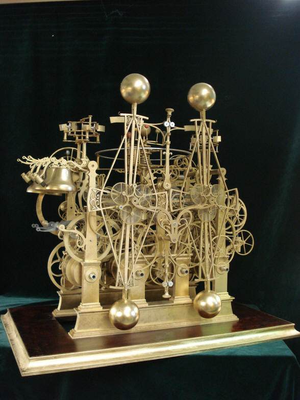
Pendulum spring regulator assemblies - March 2016 This month we create the controllers to adjust the tension in the upper and lower pendulum coil springs. We now enter a phase in the project where we are preparing to complete the time train to the point where we will be able to properly rate the clock. Over the past several years the clock has been running on an intermittent basis, but with no regard to actual timekeeping abilities. To this point there have been one pair of pendulum springs, one on the upper and one on the lower pendulum assemblies. Now we must split these springs into two pair, or four springs. This will allow for the accommodation of spring tension adjusters to permit fine tuning of the pendulum's isochronism. At this point we will also need to create all of the various attachment points to connect the springs to the adjusters as well as anchorage to the pendulums themselves. This will be dealt with in the April installment. Finally all of the escapement components that are past the drive remontoire, that is the pendulums, escapement wheels, grasshopper escapement pallets as well as the antifriction wheel assemblies must all be brought to their final finish. This is necessary since the removal of metal in this process will affect performance. This last step is what will slow down progress considerably over the next few months. Unfortunately, the final finish and polish can, depending on the geometry of the part, take longer than the creation of the original part. The period of the dual compound pendulums are currently determined by both the inherent frequency of the two coil springs attached to both the top and bottom of the pendulums as well as the pendulum configuration. Additional adjustments are accomplished with the sliding weights mounted to the pendulum diagonals; first to achieve poising of each pendulum and then gross rating in relation to the fine rating achieved through the adjustment of the effective coil tension. The rate of the pendulums is controlled chiefly by the pendulum configuration. These controllers will be largely used to achieve isochronism.
Pictured above is a concept for the spring regulators. I had provided a rough sketch on August 13, 2005 two years before construction had begun in July of 2007. Both concepts were a type of scissors design which would control both the upper and lower balance springs simultaneously. I included the header with the diagrams to show the way ideas were filed for the clock as I went along. Page one began on November 14, 2003 and ended with page 106 on July 8, 2010. By that time construction was well underway and most of the major design concepts were complete. However Buchanan had other ideas and these were reflected early on.
When I searched through the construction files, I found that back in March 2009 when the second wooden mockup was created for the frame redesign; one can plainly see the regulators. So Buchanan had already thought through this detail exactly seven years ago. It appears that the regulators are independent of each other. So my question is how do we achieve isochronism? I had thought that once the springs were properly adjusted on both the upper and lower areas of the pendulum balances that any adjuster should be slaved together between the two. At he time, nearly eleven years ago, this seemed like a good idea. The problem with this idea is the fact that as the machine now stands there are too many obstructions between the upper and lower spring regulation devices to allow for a mechanical connection between the two. We will mitigate this problem by making the adjustment readings very accurate on each regulator.
One can see in the second photo the regulator taking shape according to the mockup design of March 2009.
What
is shown
is a double pulley between the springs with a band
from each spring passing around its own pulley. The bands then pass
downwards around two more pulleys which centralise the bands so that
they
can attach to an adjustable pull block.
Next there will be
a slotted dial plate, covering the adjustment screw, with calibrations to
show the position of the pull block. All this
will be
mounted on a small plate which will be held with pillars onto the beat plate
bracket and a similar bracket on the lower springs.
Here Buchanan
turns to the CAD-CAM equipment for creation of the vernier scales and fine
engraving. The initial main scale layout is depicted on the computer screen
and then details are overlaid, second photo.
Here the inner vernier
scale sliders are being milled with the completed slider inserted into the
main scale
The first photo shows
the two vernier scales used in the spring adjusters. Notice the numbers are
mirrored to each other since one will read from the top of the balances and
the other the bottom. The next photo shows a batch of twenty 1.6mm screws
and one hundred twenty 0.85mm screws. Do these look a bit reminiscent of Petri dishes with
bacteria growing on a medium?
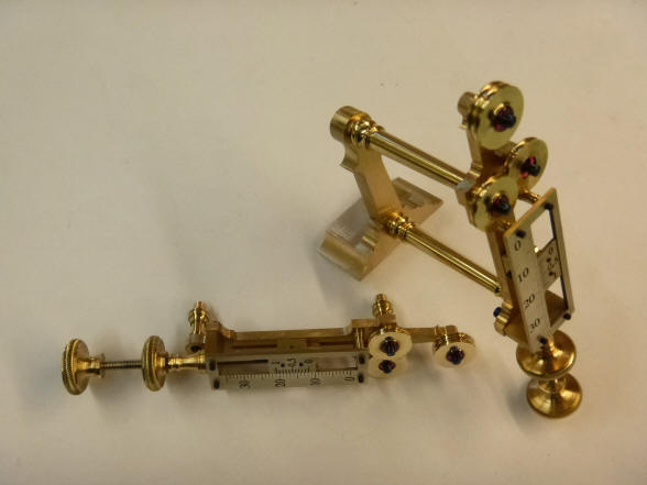
A long fine thread rod
will serve to move the vernier scale along the main scale’s length.
Here the threaded rods
are positioned below the triple pulley set upon the brass blank backboard.
Next the knurled thumb and locking screws are attached. The outer knurl
serves as a locking device and is threaded on the rod while the inner knurl
is secured to the rod and turns it. This is the same arrangement Buchanan
used for fine adjustments in the
bell hammer assemblies completed in April
of 2014.
The lower spring
adjuster is complete, but still in the grey.
The upper regulator is
now mounted to the rear of the pendulum beat plate support bracket. The
mechanism is not yet integrated into the springs, but only seen behind the
single spring still connecting both pendulums. The regulator will later be
spliced into the single spring resulting in a pair of springs replacing the
one seen here; one on each side of the adjuster. A while back I had
contemplated the possibility of eliminating the beat plates thinking they
may be cluttering this area. Or that they looked a bit like a pair of
eyebrows. Well this development pretty much supplants any thoughts in that
direction! The bracket is still the original plastic mockup from 2000.
This video shows the upper spring regulator assembly attached to the movement. The pendulums are working but the regulator is not yet attached. The final arrangement will require a new split spring.
Now Buchanan makes the pendulum beat plate support structure. Up to this point this has been a plastic mockup since march 2009. Buchanan describes the process using the new CAD-CAM equipment: 1. I draw the mechanical parts.
2. We pencil in the arty parts, first photo. 3. I make a transparent
photocopy of the pencil drawing, next photo. 4. I place the transparency on
the computer screen and align my first computer drawing with the
transparency. 5. I trace around the arty bits. 6. I mirror any parts that
are symmetrical. 7. We send the drawing to the CAM program the program that
instructs the mill what to do, last photo. 8. I send the Cam file to the CNC
mill. I am now busy setting up
the mill to machine the part. I am making a 5mm thick central bracket
and 2 thin brass plates to hold the enamel beat plates.
Buchanan has begun to incorporate the limited use of CAD-CAM. The first instance was in the creation of three identical parts in the perpetual calendar last year. Next the fine engraving needed for the small chapter rings within the tellurian assembly lent itself well for purpose as well as the vernier scales for the spring regulators.. The beat plates and rear support bracket are the first use of this technique for a substantial part.
Here we have the computer aided mill cutting out the outline of the beat plate bracket. This is the first time this technique has been used for a large part in this project and has only been used for a handful of small repetitive parts in the past. This project is so far along that it will remain nearly 100% a hand made effort.
Here the sector-shaped beat plate holders themselves are milled out. Next one is fitted to the left side of the bracket. Notice how Buchanan uses two parts when he easily could have made the entire bracket from one piece including the beat plate backboards as was done when it was made in mockup form out of plastic. Later the sector sections will hold scales made of fired enamel which were completed in June of 2013.
The completed bracket with attached beat plates in place. Views from rear three-quarter and front elevations.
Up to this point the beat plate bracket was attached to the movement with plain brass pillars. In July of 2013 we decided to change the material of the main frame cross pillars from brass to stainless steel to add visual contrast between the frames and the cross pillars. This lent to a replacement of other smaller horizontally mounted pillars which to this point were brass.
The first photo shows how having the pillar remade in stainless steel nicely matches and offers a continuance to the steel pillar behind it. A lower pillar, while having no matching pillar behind it as the one above, was also remade to match. The next photo shows a beautiful blue colored screw. This is exactly the color I was looking for all along! Compare this to the pale purple one in the prior photo. This is an important development because Buchanan now has a color standard to shoot for. Until this point I had not seen the ‘electric blue’ that I was looking for. Back in April of 2008 we ran a series of tests on screws to attain the right color and came close, but this example is superior.
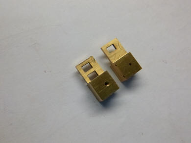
Now begins the final finishing work on the spring regulators. An EDM machine in the first photo is used to create the small square holes needed in the part that will connect the springs to the regulators.
This series of six
photos shows the evolution in the creation of decorative machining that goes
into the pillars used in the spring regulators.
Here are the components composing the spring regulators. These total 75 parts.
One can see in the second photo the vernier scales silvered and black waxed.
Lower completed regulator, but the spring is not yet attached.
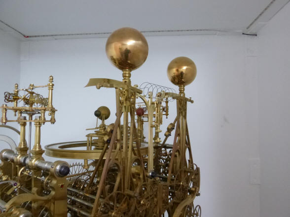
Upper regulator, again the spring has yet to be re-fabricated into two sections in order to be attached to the regulator. In the background one can see the mockup orrery still existing in the original wood model made in July 2006. This is the last mockup module still existing within the movement.
The regulators are the only components on the rear of the machine that incorporate any type of dial work. -oOo- As the clock is progressing we are looking toward the finishing touches for the tellurian and orrery. Below are some materials we are beginning to collect for the various spheres to represent the Sun, Earth and other planets and moons of the solar system. I have decided that we would use semi-precious stones for these with the exception of the Earth within the tellurian which will also be a natural organic material.
This is a large piece of Mammoth ivory. If it were a few years ago we could have gone straight to ivory, but this material is now banned from import into the United States. We plan to make a sphere similar to the mockup that has been used. The topography of the continents will be milled out of the surface and then the continental outlines as well as latitude and longitude lines will be engraved, or in the case of this material, scrimshawed, into the surface. There will be no political boundaries. We needed a fairly large piece in order to get an area in the center with no flaws or cracks for a sphere of about 1.5" or 3.5 cm.
These photos show several other stones we are considering. The first photo is a beautiful fire opal. Considering that Buchanan is in Australia there should be a ready supply as Australia is a major producer for these. The earth globe on the orrery will be made from this greenish-blue stone. The scintillation of this stone will be a real eye catcher. Next are a couple of spheres of rutilated citrine. These are not of the color or quality we want.
Next is a moonstone
which could be useful for the moons of Jupiter and Saturn. My opinion is to
let all of these be of the same color stone so as to not have too many
colors distracting from the rest of the orrery. The next photo shows other
pieces of agate. I still want to see if we could get a nice banded agate
sphere for Jupiter. But again the diameters of all of these planets on the
orrery are very small. The only spheres of any significant size are those in
the tellurian and the Sun in the orrery. |


![]()
![]()
![]()