|
Complete tellurion assembly. Complete sidereal dual dials - February 2016 This month we finish the tellurion and complete the dual sidereal time chapter ring drives.
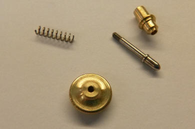
In the first photo one can see a thin dished washer inserted between the wheel and a screw-down collet. This acts as a slip clutch for the the seasons indication. One of scores of clutches used throughout the machine for safety as well as setting functions for various components and indications.
 After all the pivot holes are planted the jewel holes are prepared. First Buchanan centers on the pivot hole with a microscope, then drills the hole out undersize, then bores out the hole with a boring head as seen in the first photo, then reams the hole to size in a staking tool. Repeat 29 times for all jewels. Then the frames are finish filed. Everything loses a little more weight. With so many components, the slimmer each part can be, from a visual perspective, the better.
The first photo shows the 13 pillars used for the tellurion triple frame assembly. Next the two main frames ready for jewelling.
The nineteen jewels are now in place within the four frames and one cock. Next the triple frame design is readily seen from the side view.
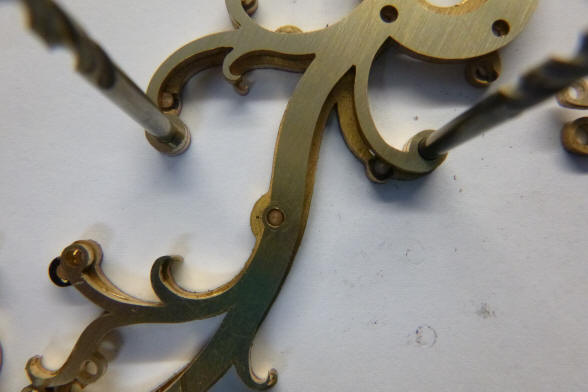
The organic ivy design found throughout the movement is continued here within this subassembly.
The bare frame shown in the prior photo is now filled out with the compliment of components for the entire complication. The celestial bodies are still mock ups and will later be replaced by Mammoth ivory and semi-precious stones.
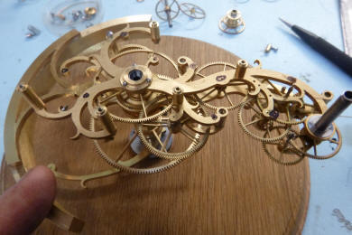
The tellurion is now complete and installed within the context of the rest of the movement. Is all this this looking a bit complex yet? Total parts count on this complication comes to 395.
Each turn of the demonstration crank equals one day. Total turns are ten. One can just see the movement of the tellurion armature counterclockwise as well as the rotation of the Earth and Moon's orbit. Although it is not clear in this clip, the calendar is also advancing at the same time. We now move on to complete the sidereal time dual rotating chapter ring drives We now turn to the completion of the sidereal time
indication. Here I will recap the process by which we created this function.
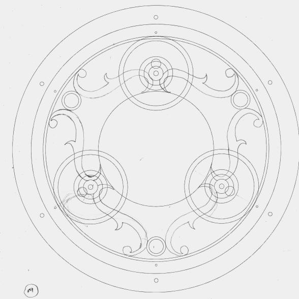
The original design envisioned in July 2006 was to have a separate, small
dial for this. It would have been delineated in the conventional twenty four
hour format. In September of 2013 I attended a symposium where a Thomas
Tompion clock was displayed that showed sidereal time on a stationary dial
with mean solar time as a clockwise rotating chapter ring concentric around
the stationary sidereal dial ring. This allowed one to read both times
simultaneously with only subtracting twelve hours from the sidereal time
reading after midyear of June 30 to convert to the twenty four hour format
since the sidereal dial was delineated in a twelve hour format. This is
necessary as the hour and minute hands are geared to rotate in a
conventional twelve hour format. Since we had already created the dial and
mechanism for the mean solar time, and this is a more important function in
our design than sidereal time, we chose to have the rotating dial for the
sidereal time which would be rotating in a counterclockwise direction. We
had assumed that we would be able to use both the hour minute and second
hands to read off both dials simultaneously and created the inner rotating
dial and all seemed well. However, after studying this I came to the
realization that this arrangement would only work with the hour hand, not the
minute or seconds. To enable a more accurate reading there must be a
separate counter rotating rings for the minutes and seconds. So a decision had to be made. Do we go with the
arrangement as made allowing a reading to the nearest five minutes or so
using just the hour hand, or do we go with additional rotating rings or dial
hands geared to sidereal time? It immediately became apparent that three
additional hands would be prohibitively expensive. We would have to create
an additional three cannon pinions within what already was a set of four
nested cannon pinions (hour, minute, second and equation). Since this was
not anticipated when these were made, the seconds would be the diameter of
medical hypodermic needle. Not only that, but the dial would have been
cluttered with seven hands. However, one additional ring for the minutes was
practical. An additional seconds ring was ruled out since it would have made
the entire dial structure with four nested chapter rings too thick; nearly
obliterating the open center section and throwing the entire sense of visual
symmetry off balance between the left and right main dials. The following is
Buchanan's beautiful solution to the problem, a classic case of ‘making
lemonade out of lemons’. Buchanan’s solution was
to create a rotating cage driven by the current sidereal hour and within
this cage are three rollers which support a central hub. That hub is driven
separately to display sidereal minutes.
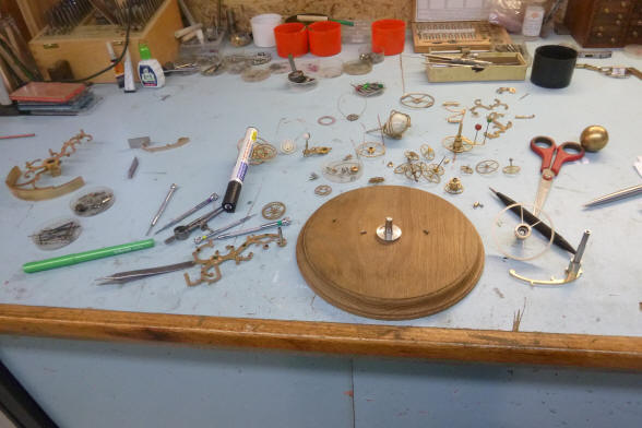
The parts begin to be
made. Notice the number 240 and 256 in red on each toothed disc. These are
the number of teeth cut into each rim. Next the rollers and roller cage
begin to be fabricated.
These photos show how
the cage rollers are mounted. Each of the three roller’s arbors are attached
at one end with a countersunk foot that is then secured by a screw, red
arrow.
The carriage is beginning to take shape. Notice the jewelling on the rollers supporting the center hub.
Now begins the spoking out process. The first photo shows the jig Buchanan uses to accurately scribe out spokes. The center steel rule has an adjustment screw on both ends so as to accurately have the edge perfectly bisect the center pin. The pins arranged around the outer perimeter allow Buchanan to select any number of spoke combinations from three to six and more. Next is a large and amazingly delicate 256 toothed wheel showing a completely missing center section. This will later hold the rear roller cage frame.
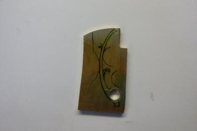
Now the artistic aspect
begins; the fun part! Buchanan's talents are put to work making beautiful
the center rotating cage controlling the sidereal hour chapter ring.
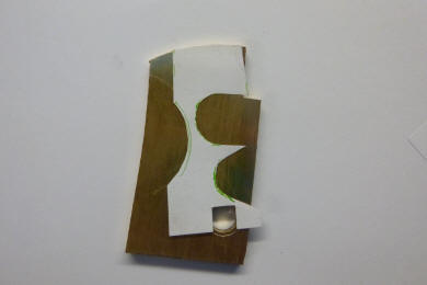
The final design is
shown within the context of the wheel that will support it as its center; the
same wheel as was shown in Buchanan's hand six photos prior. Next that
design is transferred onto the cage blank and later will be scribed onto the
surface of the metal.
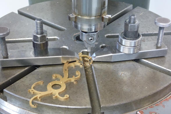
The decorative
curvilinear shapes now have to be hand filed to final profile after being
cut out from the brass blank on the fret saw. Buchanan makes extensive use
of a fleet of files, first photo. An array of filing buttons is needed to
help shape each curve. In the second photo a steel cylinder is affixed to
each side of a desired, rounded area on the rear roller cage frame, and front
frame in the third photo. Buchanan will file around this cylinder to achieve
a near perfectly round profile for each area that requires this particular
shape. In this case it is the three pivot points for the cage rollers. I
stress that the contours are near perfect with the slight imperfections that
are always present with hand work. These variances are highly desirable as
they lend to the movement being recognizable as being made by a master
craftsman and not a computer-aided machine. To my eye one cannot ever be
confused with the other.
Next the completed
decorative front cage frame and its setting within the center of the wheel
for the hour chapter ring. It is this type of work that sets Buchanan apart from the rest.
There are 68 parts that
compose the sidereal roller cage and twin rotating, concentric chapter ring
platters. There are additional wheels that derive the sidereal minute from
the original sidereal hour. The following six
photos show the build out of the roller cage driving the sidereal hours and
center hub for the sidereal minutes.
First the cage drive gear has the rear decorative cage plate assembly mounted to it. Then the part is flipped over and the three cage rollers are installed. Next the center hub is inserted.
Next the upper decorative cage plate is installed and next a three quarter view. Finally the part is again flipped over to the rear view and the center hub’s drive wheel is attached. The following photos show associated gearing and
platters which attach to the roller cage and center hub assembly.
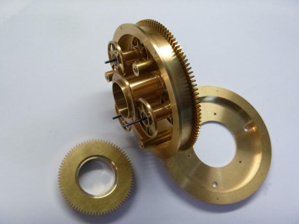
The large wheel shown
here is driven by the decorative front roller cage mounted to its center.
Notice that this wheel has a smooth rim. Upon this wheel is mounted the
sidereal hour chapter ring support platter.
Next the same
perspective from the rear is kept and the roller cage assembly is installed.
The sidereal hour and minute drive wheels are seen in the center foreground.
The part in
the prior photo is seen just below the smooth, larger wheel described above.
The hour chapter ring
platter is attached to the outer smooth wheel in the prior photo. Next the
entire assembly is flipped over to reveal the attachment points of the two
rotating platters.
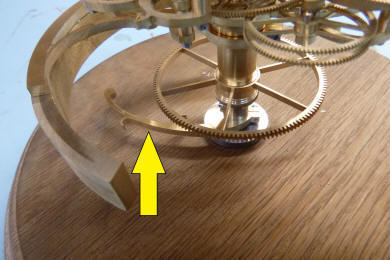
The cage assembly is now installed within the machine.
Next is the 240 toothed wheel and it is used
to derive the sidereal minutes from the sidereal hour. This is the opposite
of conventional motion work where the hours are derived from the minute
gearing. Conventional engineering would expect this where the faster rotating gear
with more torque (minutes) would drive the slower wheel. However the
sidereal hour was already constructed, and fortunately there was plenty of
power available to allow for this reversal.
The first photo shows
the careful planting of the derivative minute wheel. Next the wheel installed, rear
view.
The sidereal hour and minute counterclockwise
rotating platters are shown. Next dressed up
with dials. Only the mean solar dial is real enamel. The sidereal chapter
rings are mocked up in paper and still have to be made in fired enamel. All
of the dial bezels are also wooden mockups, yet to be fabricated in a
decorative metal design.
|


![]()
![]()
![]()