|
POUVILLON RESTORATION PROJECT - November 2011 Complete restoration of the Easter calculator: the release lever, annual cam pack, recreate perpetual calendar mechanism for the calculator I have asked Buchanan to provide what I call a 'forensic' report. That is to record his observations as he goes along. I will provide the .MP3 audio file for each segment but just in case your security settings will not allow you to open this file I have also transcribed each session. My additional comments will be inserted into the text from time to time and this will be in red text. Buchanan refers to each photo by the number of that photo which can be followed by each photo above the captioned text. The .mp3 audio file will appear in blue text.MP3. Click on this text and you can then follow along with the audio file by scrolling downward through the photos as they are narrated one by one in the voice of the restorer. This month we complete the Easter calculator repairs and restorations; culminating in the replacement of the mechanism necessary to make the Easter calculator perpetual. This mechanism was mentioned by Mr. Pouvillon in two newspaper article interviews in the mid 1950's. Check the first entry on the INDEX page to see these articles. Below we deal with the completion of repairs and restoration of missing components for the Easter calculator.
Pouvillon-53-001.MP3 . Photo 53 001.
We have a photograph of the crank lever that operates the equation of time
dial and here we have a Pouvillon style clevis which we hope to use the
style of for the trip mechanism for the Easter calculator.
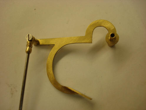
Photo 53 002. Here we have the
new lever, the new clevis that connects the Easter calculator to its trip
lever.
Photo 53 005.
The lower end of the connecting lever attached to the warning lever on the
Easter calculator.
Photo 53 006.
Another view of the connecting mechanism from the Easter trip.
Photo 53 008. A photograph of
the trip cam and also its connecting rod.
Photo 53 010.
A view from the opposite side of the clock to show the comparative size of
the lever with the operating lever for the equation of time dial. We have a
considerable amount of distortion in these photographs. So when we take a
photograph from the opposite side of the clock the Easter lever looks
thicker than the equation of time lever.
Photo 32 012. Another view of
the release lever and the ‘U’ bend to bring it over the top of the sunset
rocking lever. This second photo is a better
representation of the two levers, Pouvillon’s lever in the foreground with
our trip lever in the background.
Photo 53 014.
Just a general photograph to show the complete Easter trip mechanism. Please
note we must still skeletonize the Easter trip snail.
Photo 53 015. Just a general
photograph of the complexity of the movement. Still missing in this
photograph is most of the equation of time differential mechanism.
Pouvillon-54-001.MP3. Photo 54 001.
Here we have the final completed cam pack. This is, of course, before its
polish. You can see a locating pin between each collect and each cam. This
is to make sure we can reassemble the cam pack correctly because in the
arbor we have a dimple that locates each locking screw so there is only one
possible way to assemble this whole cam; which facilitates setting up the
cam pack if one ever disassembles it for maintenance reasons.
Photo 54 003. Another photograph
of the completed cam pack. Photo 54
004. Another view of the cam pack of interest to note are the long
pivots on this arbor which are very similar to the long, thin pivots Mr.
Pouvillon uses on the main clock movement.
Photo 54 008.
Another photograph to give an indication of the size of the cam pack.
One can see how such an eye-catching part might
have gone missing sometime after the clock wound up partially disassembled
in the charity shop after Pouvillon’s death.
Buchanan now begins additional work within the Easter calculator.
Pouvillon-55-001.MP3.
Photo 55 001.
This series of photographs was taken for the purpose of having a record of
the disassembly process and to make sure we reassemble the whole calculator
correctly. This is the upper dial, the Dominical Number dial and shows its
operating lever and pawl. I’ve already removed its pivot screw or shoulder
screw. And, of course, we can see the return springs and the pawl return
springs. Photo 55 002. This is
the lower portion of the mechanism. Interesting is this little bent bracket
right in the center of the photograph through which the brass rod passes.
The rod end kept in place with a taper pin. This provides a more or less
parallel motion for the feed pawl for the first day of the year dial. We can
also see counterweighted pawls. They are used extensively in this mechanism.
Photo 55 006.
Here we have the other end of the rocking lever, also stamped 19. It’s
operating pawl, which of course has fallen down, because the ratchet wheel
is not in place. Of note is the pressed-flat operating levers also a pawl
right in the foreground whose weights have been doubled up to make it
operate more positively.
Photo 55 007.
Another operating lever, its associated pawls and return springs.
Photo 55 008. Another feed pawl
mechanism and its return spring. This is the rod we discussed earlier that
has the horizontal motion. I think if one considers how much use is made of
flat strip that is only bent and not machined from the solid we see what I
think indicates Mr. Pouvillon’s desire to have a mechanism completed as
early,
quickly,
as possible. This would refer to his desire in
one of the newspaper articles to have the Easter calculator completed before
his death. Both of these
articles refer to his finding, or creating the last part needed to make his
calculator perpetual. We explore this as we restore the calculator, see
description beginning at photo 56 001.
Photo 55 012.
Another photograph of the front frame and its associated clicks.
Photo 55 013 is the intermediate
wheel between the solar cycle and the Easter date disc. Of interest to note
is these two unequally spaced holes in the gear and I have no idea why they
are there. One surmises it was perhaps for a further calculation or
correction. Photo 55 014.
Another identification number pertaining to a non-return pawl.
Photo 55 015.
Another non-return pawl. Photo 55
016. One of the ratchet wheels and its arbor from the Easter calculator.
Of interest to note is on the steel arbor signs of gilding being present. It
appears that the arbor and wheel were gilded complete and gilding cleaned
off where necessary.
Photo 55 018.
This is the Easter date disc wheel and its arbor and collet. Here we have a
hexagonal nut used as a spacer to control end shake as the arbor is carried
through the front frame at complete thickness to provide a ridged mounting
for the Easter date disc and also an extended portion on the collet on inner
edge where we believe a component is missing.
We believe this hex nut is something a later
‘repairer’ had inserted.
Buchanan
now addresses the missing calculator's perpetual mechanism. Pouvillon refers
to his having created such a mechanism in two newspaper articles we have
dating from 1953 and 1955. So while we know the calculator was substantially
completed by 1946 from the date stamped on the Easter date disc, Pouvillon
was still making changes until at least 1954 when he would have been 76
years old.
Pouvillon-56-001.MP3. Photo 56 001. This is a cam fitted to provide
a correction to the Epact dial to make the Easter calculator a perpetual
calculator for at least 400 years or until we have a missed leap year.
This is attached to the empty collet we
examined in detail in last
month’s installment,
see photo 49 006.
This cam rotates
once in 19 years and provides the correction needed every 19 years to the
epact dial, see photos 56 010, 012 and 013 below.
Photo 55 002. Another view
of the Epact correction cam.
Photo 56 005. Here we have the
lever and its connecting mounting on its arbor. The pin extending towards us
actually becomes an adjustable stop for the sector gear that feeds the Epact
hand.
Photo 56 006.
Another view from the opposite side of the lever and its operating rod.
We’ve used screws that are virtually identical to Mr. Pouvillon’s screws
used on this mechanism all I believe salvaged from old pocket watches.
Photo 56 008. Here we have that
new correction rocking lever pivoted on the unused portion of the center
arbor collet. We have the cam on the lower right hand side wheel with its
notch and we have the correcting lever mechanism unfortunately mounted on
the front plate which is not visible in this photograph.
Photo 56 009. Here we have the connecting rod with its attached lower end to the rocking lever. Photo 56 010. Here we have another view of the rocking lever and if we look at the arbor with the small gear on it we can see the lever projecting upwards diagonally, marked 30. This lever drops or rotates clockwise until it rests on the stop pin on our new lever and when the correction comes into play this pin drops a little to provide an extra tooth of feed to the 32 tooth gear and instead of feeding 11 teeth in a particular year, once in 19 years it will feed 12 teeth. And this gives us a perpetual Epact dial, which gives us a perpetual calculator. Pouvillon-56-012.MP3. Photo 56 012. Here we have a pointer showing the feed pawl lever resting against the stop and this is in the 12 tooth feed position.
Photo 56 013.
Here we have the stop raised in the 11 tooth feed position.
Photo 56 015.
If you look through the aperture in the spoke of the large gear in the
foreground you’ll see the rocking lever and its pin resting on the
correction cam and about to drop with the edge into the notch. This is the
position occupied during 18 years while the gear is rotating until we reach
this position.
Photo
56 016. Unfortunately in the shadow a little but here we have the
rocking lever with a pin in the notch in this position we have a 12 tooth
feed to the Epact.
|