|
Continue tellurion assembly, begin solar and lunar eclipse demo - November 2015 This month we continue the fabrication of the tellurion complication.
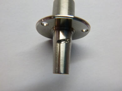
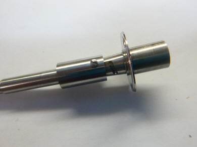
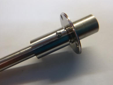
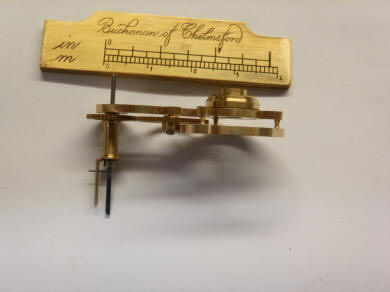
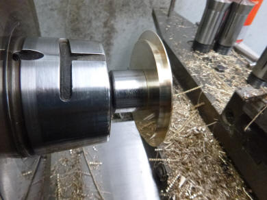
These photos show the
central mounting for the tellurion. It can be removed as a single unit and
released with a simple twist.
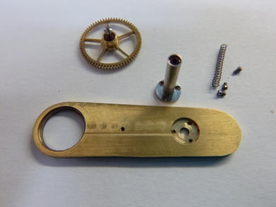
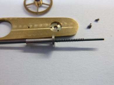
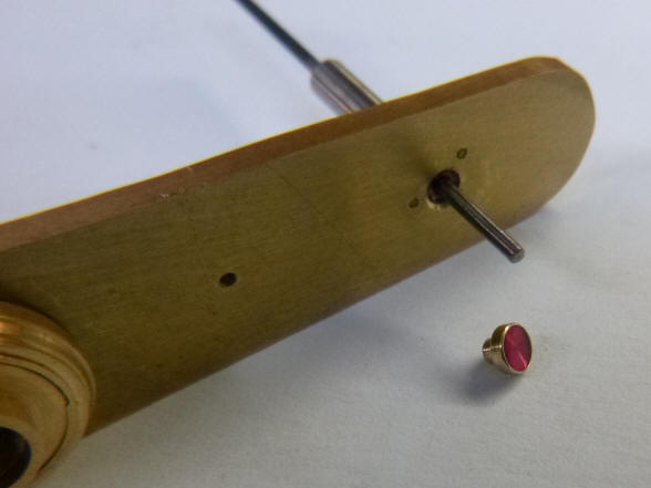
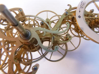
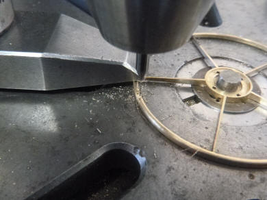
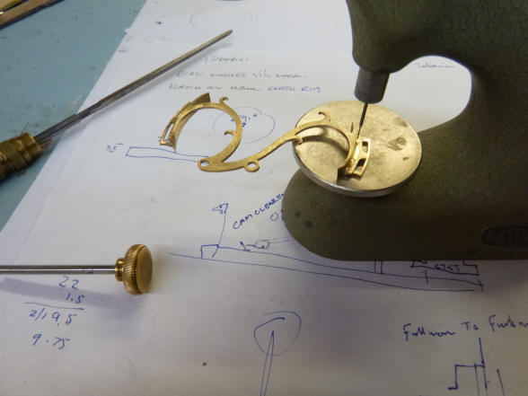
Buchanan now continues
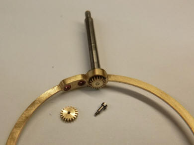
with the moon armature. The first photo shows one of three holes being
drilled for screws that will secure the hollow post upon which the moon’s
mounting will slide. Notice how close the drill is to the hollow post, next
a few of the completed components with the hollow post shown. The third
photo shows a spring that will bias the rod upon which the moon is secured
within the hollow post. That spring is needed to hold the moon against the
node ring upon which it will ride. Most tellurions are horizontally mounted so
the weight of the moon and its mount use the force of gravity to ride on the
node ring. But since this one will be rotated 900 we must use a
spring to keep it seated on the ring.
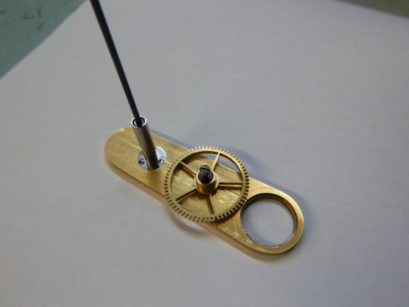
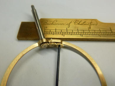
The slider is now
mounted within the tube. Notice that a jewel is used here. We use no
metal-to-metal contacting surfaces where there is sliding or rotational
surface contact. Those would need oil, and we are avoiding oil in this
machine. The next photo shows the beginnings of the artwork for the ring set
that will surround the Earth globe.
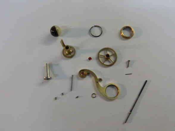
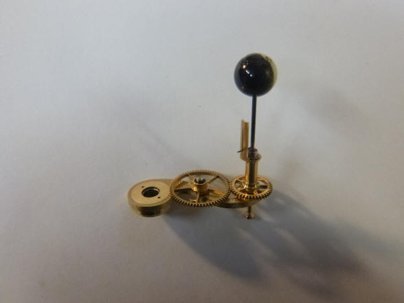
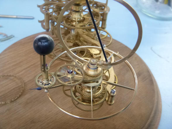
The completed Moon
armature assembly ready for installation into the rest of the tellurion.
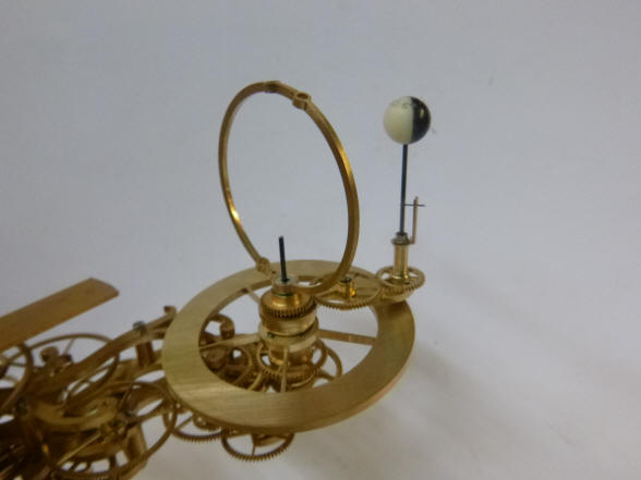
Next the unit is installed. Notice the guide fork installed on the tube that
has the sliding rod for the Moon. The circular disc is the node ring which
is angled at 5.140
reflecting the tilt of the Moon’s orbit to the Earth along the
ecliptic. This ring is what will move the Moon up and down on the jewel
slider as it orbits the Earth. That ring also rotates once every 346.6 days
representing when the nodes makes a full circle in relation to the Sun. The
combination of this cycle and the cycle of Earth’s orbit around the Sun in
365.24 days produces the
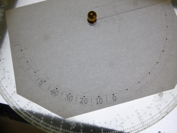
The first photo shows the top set of nested bearings used in this assembly. The center photo shows part of the curvilinear multi-level frame, next a mockup of the node dial.
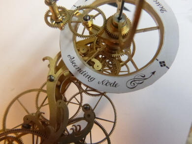
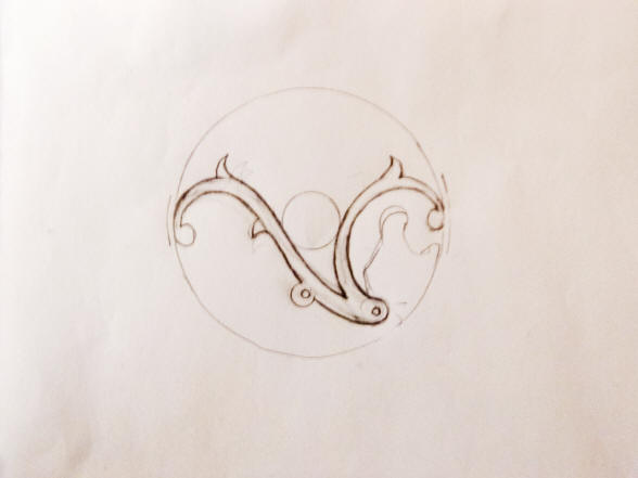
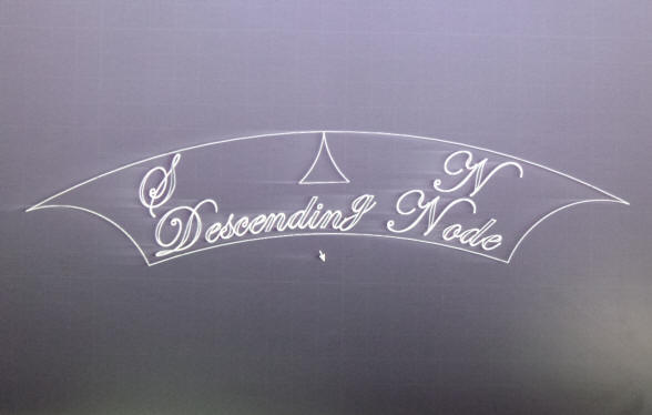
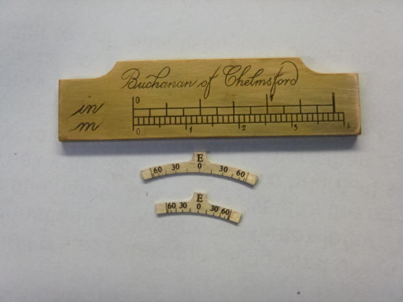
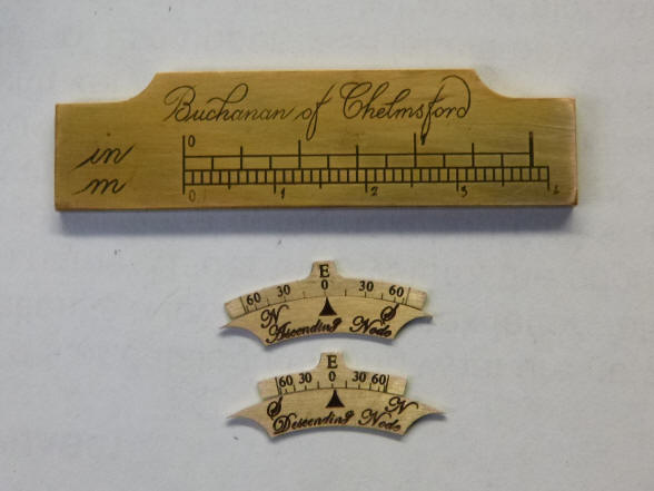
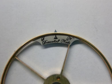
I received several
photos of the tellurion, in particular Buchanan’s design for the moon’s node
cam disk. In a similar nod to prior makers, that disk has a thin enamel
dial. He has written “Ascending Node and “Descending Node”. The actual point
on the cam where this occurs is marked with a diamond pattern identical to
that found on the main tellurian dial. It is an elegant design and ties in
nicely with the main dial work. He indicated that there will need to be a
counterweight to the earth/ Moon system attached to the rotating armature.
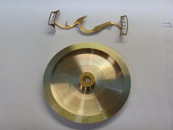
He then suggested that we use a sickle-shaped weight with an enamel cover as
a counter-point to the enamel dial ring for the Moon’s nodes.
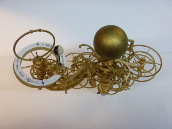
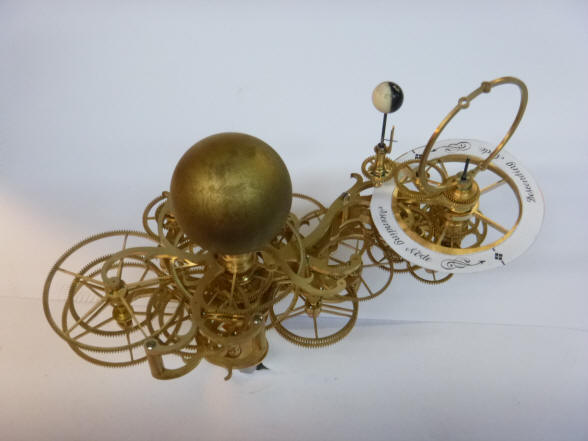
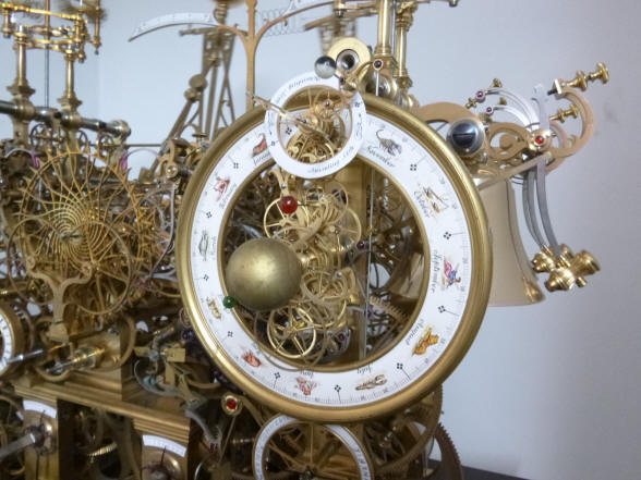
At that point I was beginning to wonder if the node ring was looking a bit too heavy; making the entire Earth/ Moon system look cluttered; especially if an enamel covered sickle counterweight is included at the opposite end of the armature. This was especially brought to my attention with the photos of the tellurion mounted upon the clock. I suggested that we try eliminating the enamel dial ring entirely; replacing it with a thin rim upon which the moon would ride to give the inclined lunar orbit. The position of the ascending and descending nodes, and the position of the Moon’s orbit relative to the ecliptic could be denoted by the astrological symbol for the dragon’s head which looks very much like the Greek letter Omega. That sign in the inverted direction depicts the descending node.
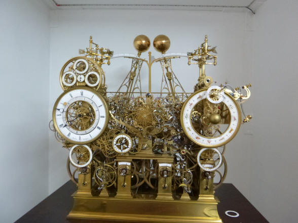
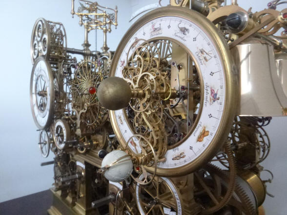
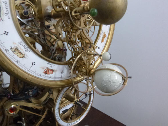
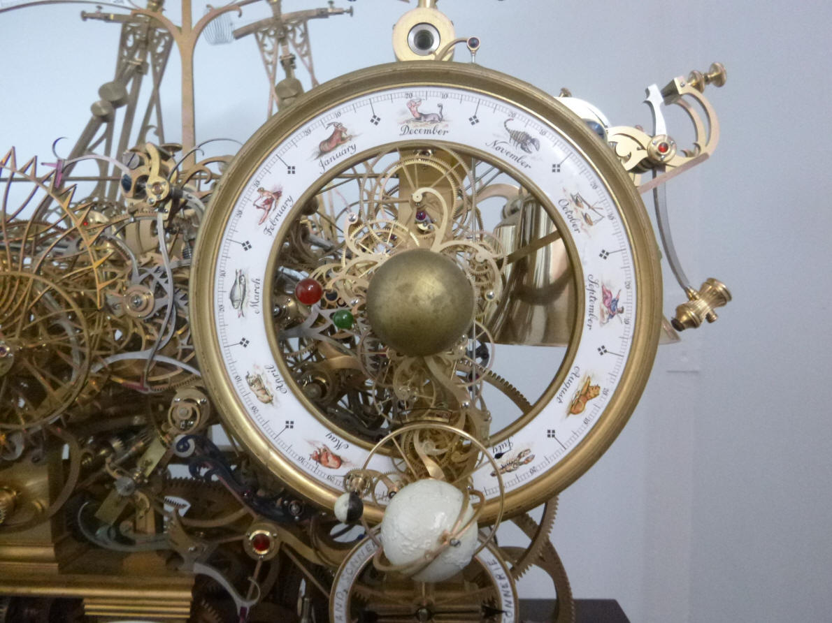
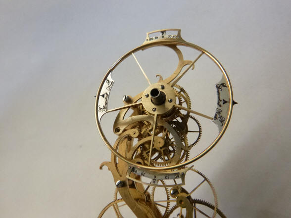
An overall front elevation of the dial work. The next photo shows the detailed turning for each of the two inner planet stalk mounts.
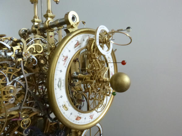
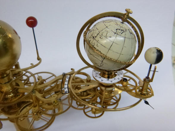
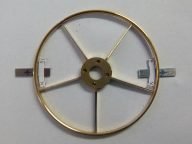
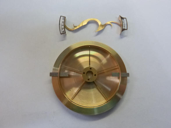
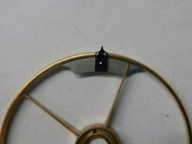
Buchanan now has substituted a thin rim for the the enamel dial chapter ring. I like this much better. It eliminates the clutter around the Earth / Moon system. I also asked that the rim have a rounded edge for the perimeter, like a steering wheel. We will still be able to include the information on the ascending, descending nodes within the framework of the eclipse prediction indicators that are yet to be designed. We will also try to hide the sickle counterweight behind the main dial. The globe is now painted white to simulate the eventual Walrus tusk material which will be scrimshawed to reveal continental and longitude, latitude details. This is in keeping with our intention to have all of the celestial bodies made of natural materials.
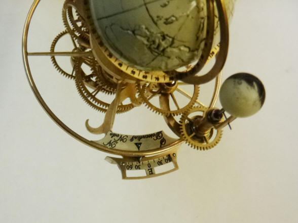
There are two sector
‘windows’ that are attached to the base of the mounting for the Earth, and parallel to the ecliptic for the Earth
and these do not move. The ecliptic
is an imaginary line running from the center of the Sun to the center of the
Earth. As the Earth rotates that line traces out a circle around the Earth. The slightly larger window resides between the Earth
and Sun and is used for the solar eclipse reading. The other is 1800
around, is a bit smaller and is used for the lunar eclipse reading. Each
window is 34.340 and 22.960 around the circumference
of the Earth. Since there are 365.242 days in the tropical year, these
translate into 32 and 22 day windows. The two windows represent what is
known as the ‘
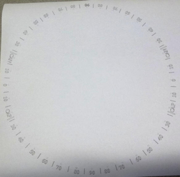
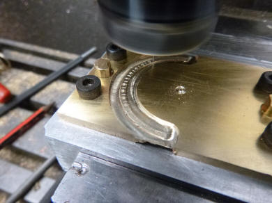
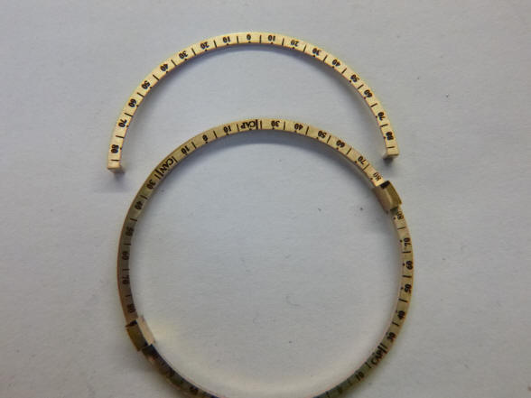
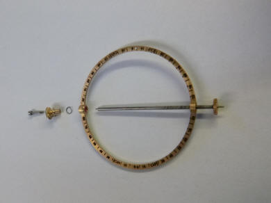
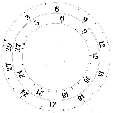
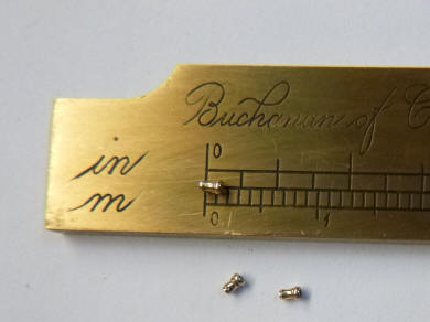
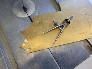
The artwork for the
Earth latitude and longitude rings is now complete. One must remember that
these are very small, just over 1.5” or 4 cm in diameter and the surface
upon which the numerals are engraved only 2 mm wide. The first is demarked
in degrees 0 through 180 running clockwise and anticlockwise and is the
equatorial ring. This is the longitudinal ring. The second is divided in
quadrants with 0 through 90 degrees. The letters CAP, for the Tropic of
Capricorn and CAN for the Tropic of Cancer at the 20 degree locations. This
is the latitudinal ring.
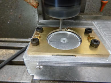
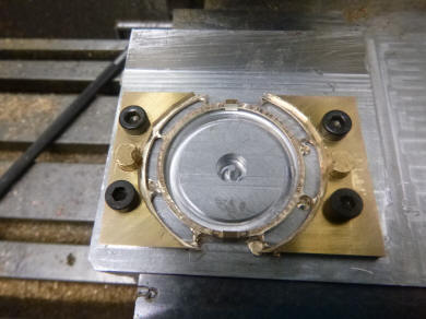
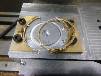
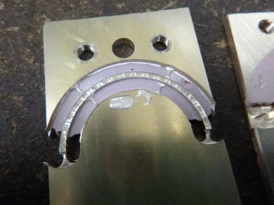
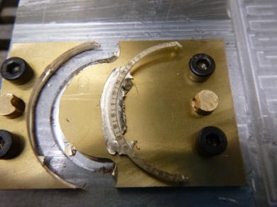
These six photos show
the engraving process for the Earth rings. At this small scale a computer
controlled engraver was the only practical solution. After the rings are
engraved they are milled out from the brass blank.
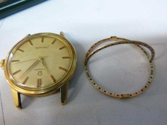
The small scale is
revealed by the first photo; no larger than a wristwatch. Next some of the
finished engravings on the rings.
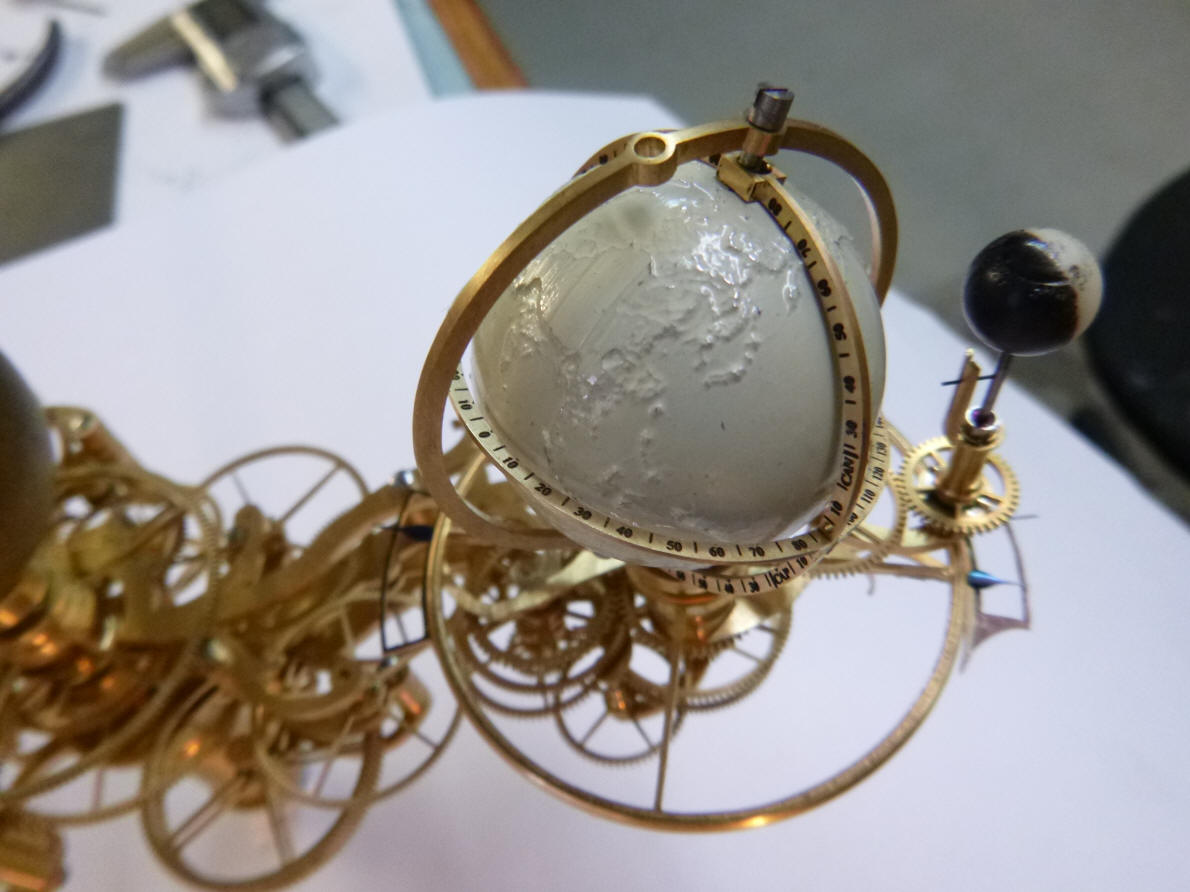
The initial trial fitting of latitudinal and
longitudinal engraved rings.
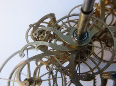
Here we see the drive for earth’s rotation, next the axis. All pivots for the gears and axis are jeweled.
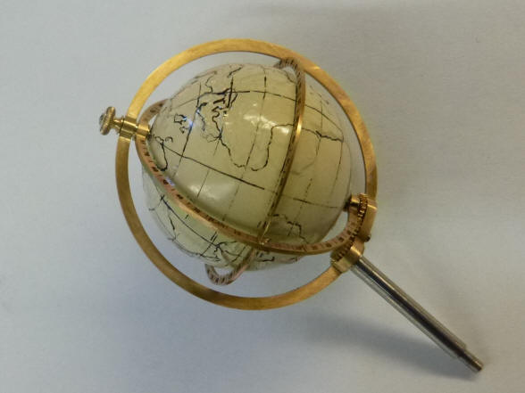
The earth support mounted to the tellurion, next the Earth
mounted within the rings. The knurl knob allows one to position the inner two rings at
will. This will allow the user to set the inner ring at any location for the
‘zero’ time reading. They also serve to interpolate between the latitude
degrees readings given from the eclipse season window onto the actual
location of the Earth’s surface. Buchanan has decided to fill in the
continental, longitude and latitude lines on the globe. Again this is merely
a rough mockup. At this juncture we will also be adding another two complications to the tellurian, two dials to indicate the synodic and sidereal orbit of the Moon.. The synodic dial will have 29.53 days and the sidereal would be 27.32 days. The dials will move in relation to each other and be located at the base of the earth.
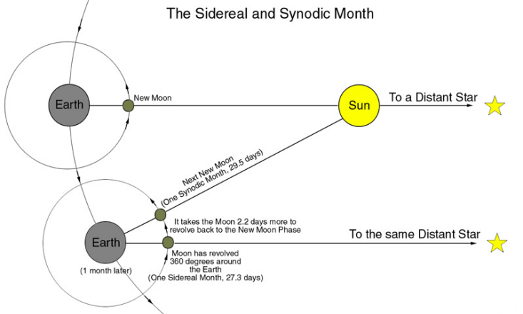
The diagram explains the difference between the synodic
and sidereal lunar months. This strongly parallels the relationship between
sidereal and mean solar time. In both instances the sidereal period is
related the movement of a body, in this case the orbit of the Moon as it
relates to the distant fixed stars. In this case the orbit of the Moon as it
relates to the fixed stars takes 27.3 days, whereas it takes 29.5 days for
the Moon to go from one New Moon (or Full Moon) to the next New Moon. This
occurs because of the additional distance the Earth, and therefore the Moon,
has rotated around the Sun.
In this video for the first time we demonstrate the interaction between the Moon's node ring indicator, the season eclipse window and the position of the Moon in predicting eclipses. The system is very preliminary and there are still obvious glitches, but the basics are here. The latitude rings will later be used to interpolate the position on the face of the Earth an eclipse will take place as well as the length of its path.
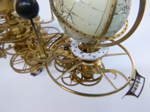
Now begins the fabrication of the components for both the eclipse prediction function and the synodic, sidereal Moon orbit dial work. In these photos we see the dial base as well as the tiny pillars that will support that dial being incorporated into the Moon armature for the synodic, sidereal dials. Even at the scale of one millimeter, the pillars are finely turned. It is at these scales that the workmanship and attention to detail separate this clock from most others that have been built.
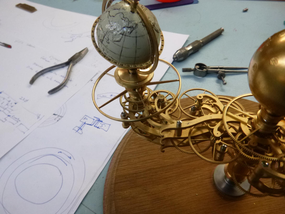
The dial base is now installed on the tellurion. Note the hand rendered drawings in the background, the same design methods used by horologists for millennia. While modern methods are not eschewed, the vast majority of this project is done in the traditional ways.
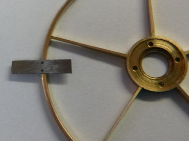
Here the node indicator hand is being fabricated. First the steel blank is drilled and then positioned upon the node ring for attachment. The size and tolerances here are extremely small.
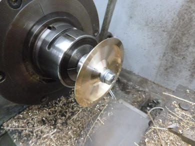
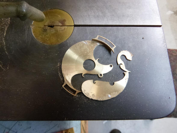
The eclipse season windows begin from a thick brass sheet. The next two photos show the turning of the flat stock into a dish-shape with a tall lip.
That lip around the edge of the dish will become the individual season windows with the balance of the rim removed. The mockup for the eclipse season windows support piece is shown above the dish with the node ring placed within the dish to check for fit in the second photo before the dish is shaped into the final part.
First a drawing for the eclipse season window support is prepared with the
dish next carefully cut away. While the location of the windows stayed in
the same positions as that on the mockup part, the actual configuration of
the part took a decidedly more decorative turn.
Notice how the raised rim of the dish now
becomes the area where the dial frames are located. 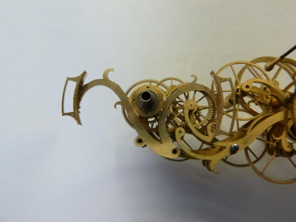
Now the eclipse season windows and support piece are checked for fit within the tellurian. Next holes are drilled and tapped for screws to secure the eclipse season sector dials. Below we will see Buchanan's use of computer aided design and manufacture, CAD-CAM, in the creation of the Earth's rings and dial work for the eclipse prediction mechanism. Up to this point there has been virtually no employment of the technology. I have emphasized in the past the hand-made nature of this project and it remains so. But in some limited applications the use of this technology allows us to do things that otherwise would be impossible or nearly so as in the case of the Earth globe. Or as it allows us to make something with a high quality standard that would be difficult by hand as in the case of very small scale engravings.
Buchanan uses a computer
simulation to determine the dial layouts for the solar and lunar eclipse
season dials. The first screen shot represents a solar eclipse, the second a
lunar eclipse. Both the Moon and Earth are divided into 24 sections equaling
150 per section. The solar eclipse season is 33 days per year
with the lunar season being 22 days. These are the times where the Moon’s
nodes are close enough in alignment to the Sun’s ecliptic that the Moon will
cause a partial to full solar eclipse or in the case of a lunar eclipse the
Earth’s umbra will cause a partial to full eclipse of the Moon. The node
ring revolves once every 346 days which is the time for the position of the
Moon’s rising or falling node to make a complete orbit all the way back to
that same position in relation to the Sun. Each season’s length translates
into 33 days/346 days x 3600 = 34.340 and 22 days/346
days x 3600 = 22.890 of a full orbit of the earth
around the Sun. These arcs are reflected within the circled areas of the
photos and translate into the size of each dial sector plate. The parallel
lines from 600 North to 600 South are projected onto
the sectors and determine where the dial degree indications will be located.
It is not a linear scale as the lines are closer together near the edges of
each dial than the center.
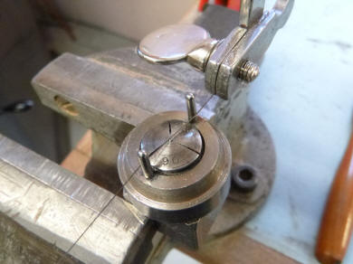
This video shows the computer controlled machine and the computer screen in real time as it creates the tiny script used on the eclipse window and node ring dials as well as the degree demarcations on the latitude and longitude Earth rings all used in our eclipse prediction assembly.
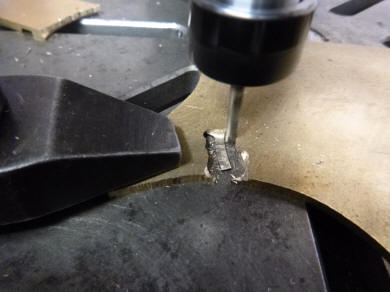
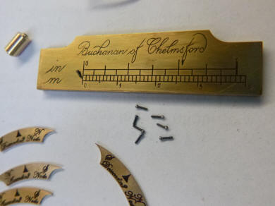
The completed dial work engraving.
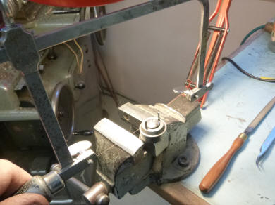
Here we see how Buchanan cuts a tiny slot in the head of a small screw using a precision hand fret saw. The tiny screw is held in the vise by a lathe collet within a jig that has the two upright pins. Those keep the thin saw blade straight and perfectly aligned down the center of the screw head. The head is less than 1 mm in diameter. These screws will secure the dial work. Here we are back to hand work and elbow grease.
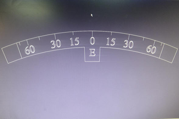
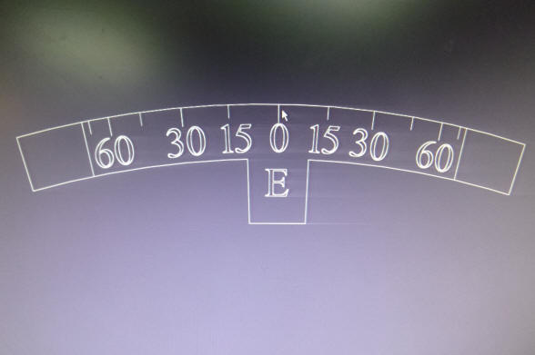
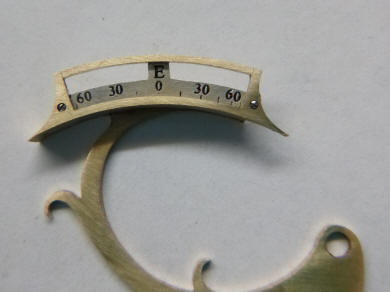
The dial work shown mounted to their respective positions. The first photo shows one of the season eclipse window dials. Next we see a node dial plate secured to the node cam ring. Notice the clever way Buchanan secures the plate, third photo. He uses the rim pointer which is secured to the underside of the rim in the first photo with two tiny screws and then uses the dark area of the dial plate pointer on the other side to hide the screw that secures the plate to the steel back of the rim pointer. This not only secured the dial plate, but allowed it to rest upon one of the spokes and below the edge of the perimeter rim; giving the entire presentation a nice reveal under the rim. This is necessary as the Moon must ride upon this perimeter without obstruction. There is no other way I could think of doing this without the evidence of screws, say on the rim’s outside perimeter secured to the edge of the dial plate. The alternative would be the use of adhesives which is not allowed in this project, all parts have to be mechanically secured in a reversible fashion.
The first photo shows all four dials in place, the pair of node ring dials at the three and nine o'clock positions and the pair of the eclipse season window dials at the six and twelve. Next the node dial is rotating counterclockwise into place over the eclipse season window dial. Nearby is the Moon, which at this point does not hav e its indicator hand yet installed moving clockwise. When the Moon passes over the 'E' tab, an eclipse takes place. That tab represents just over 40 representing the time of a typical eclipse of about 8 hours.Conditions for an Eclipse: One can predict eclipses by understanding the conditions
that make them possible. As you begin to think about these conditions, be
sure you are aware of your point of view you must imagine that you can look
up into the sky from your home on Earth and see the sun moving along the
ecliptic and the moon moving along its orbit. Since there are two nodes in the
Moon’s orbit there will be at least two solar eclipse seasons per year and
with the moon on the opposite side of the Earth, two lunar eclipse seasons.
So why do these eclipses seem so rare? The reason is that in the instance of
a solar eclipse the shadow of the moon on the Earth is extremely thin and
the duration of the eclipse very short. A typical track for a full eclipse
is only 100 to 150 miles wide (161 to 240 km) depending on how close the
Moon is to perigee and about 1000 miles long (1610 km) before the show is over.
Although a solar eclipse occurs about twice yearly, a given place on Earth
only averages one total eclipse of the Sun every 360 to 410 years. Following
are descriptions and diagrams to illustrate the concepts.
Figure
1a and b.
Eclipses can occur only near the nodes of the moon’s orbit. (a) A solar
eclipse occurs when the moon meets the sun near a node. (b) A lunar eclipse
occurs when the sun and moon are near opposite nodes. Partial eclipses are
shown here for clarity Eclipses
can only occur when the sun is near one of the nodes of the moon’s orbit. A
solar eclipse happens at new moon if the moon passes in front of the sun.
Most new moons pass too far north or too far south of the sun to cause an
eclipse. Only when the sun is near a node in the moon’s orbit can the moon
cross in front of the sun, as shown in
Figure 1a. A lunar eclipse
doesn’t happen at every full moon because most full moons pass too far north
or too far south of the ecliptic and misses Earth’s shadow. The moon can
enter Earth’s shadow only when the shadow is near a node in the moon’s
orbit, and that means the sun must be near the other node. This is shown in
Figure 1b.
So there are two conditions for an eclipse: The sun must
be crossing a node, and the moon must be crossing either the same node
(solar eclipse) or the other node (lunar eclipse). That means, of course,
that solar eclipses can occur only when the moon is new, and lunar eclipses
can occur only when the moon is full.
Figure
2a and b.
Eclipses can occur only near the nodes of the moon’s orbit. (a) A solar
eclipse occurs when the moon meets the sun near a node. (b) A lunar eclipse
occurs when the sun and moon are near opposite nodes. Partial eclipses are
shown here for clarity The
view from Space: Change your point of view
and imagine that you are looking at the orbits of Earth and the moon from a
point far away in space. You would see the moon’s orbit as a small disk
tipped at an angle to the larger disk of Earth’s orbit. As Earth orbits the
sun, the moon’s orbit remains fixed in direction. The nodes of the moon’s
orbit are the points where it passes through the plane of Earth’s orbit; an
eclipse season
occurs each time the line connecting these nodes, the line of nodes,
points toward the
sun. Study
Figure 2
and notice that
the line of nodes does not point at the sun in the example at lower left,
and no eclipses are possible. At lower right, the line of nodes points
toward the sun, and the shadows produce eclipses. The shadows of Earth and
moon, seen from space, are very long and thin, as shown in the lower part of
Figure 2. It is easy for them to miss their mark at new
moon or full moon and fail to produce an eclipse. Only during an eclipse
season, when the line of nodes points toward the sun, do the long, skinny
shadows produce eclipses.
Figure
3.
A
calendar of eclipse seasons. Each year the eclipse seasons begin about 19
days earlier. Any new moon or full moon that occurs during an eclipse season
results in an eclipse. Only total and annular eclipses are shown here.
Figure
4.
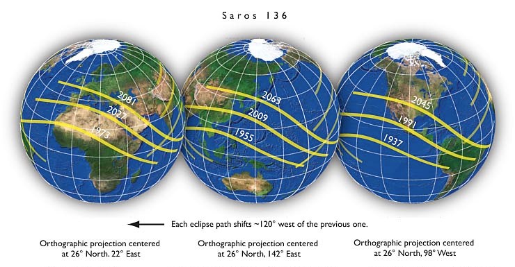
The Saros cycle at work. The total solar eclipse of March 7, 1970, recurred
after 18 years 11⅓ days over the Pacific Ocean. After another interval of 18
years 11⅓ days, the same eclipse was visible from Asia and Africa. After a
similar interval, the eclipse will again be visible from the United States If
you watched for years from your point of view in space, you would see the
orbit of the moon precess like a hubcap spinning on the
ground. This precession
is caused mostly by the gravitational influence of the sun, and it makes the
line of nodes rotate once every 18.6 years. People back on Earth see the
nodes slipping westward along the ecliptic 19.4° per year and the sun takes
only 346.62 days (an eclipse year)
to return to a node. This means that, according to the calendar, the eclipse
seasons begin about 19 days earlier every year Figure 3.
The cyclic pattern of eclipses shown in Figure 3 should give you another clue how to predict eclipses. Eclipses follow a pattern, and if you were an ancient astronomer and understood the pattern, you could predict eclipses without ever knowing what the moon was or how an orbit works. All you need know is the cycle.
The Saros Cycle:
Ancient astronomers could predict eclipses in a crude way using the eclipse seasons, but they could have been much more accurate if they recognized that eclipses occur following certain patterns. The most important of these is the Saros cycle (sometimes referred to simply as the Saros). After one Saros cycle of 18 years 11⅓ days, the pattern of eclipses repeats. In fact, Saros comes from a Greek word that means “repetition.”
The eclipses repeat because, after one Saros cycle, the moon and the
nodes of its orbit return to the same place with respect to the sun. One
saros contains 6585.321 days, which is equal to 223 lunar months. Therefore,
after one Saros cycle the moon is back to the same phase it had when the
cycle began. But one saros is also equal to 19 eclipse years. After one
Saros cycle, the sun has returned to the same place it occupied with respect
to the nodes of the moon’s orbit when the cycle began. If an eclipse occurs
on a given day, then 18 years 11⅓ days later the sun, the moon, and the
nodes of the moon’s orbit return to nearly the same relationship, and the
eclipse occurs all over again.
Although the eclipse repeats almost exactly, it is not visible from the
same place on Earth. The Saros cycle is one-third of a day longer than 18
years 11 days. When the eclipse happens again, Earth will have rotated
one-third of a turn farther east, and the eclipse will occur one-third of
the way westward around
Earth Figure 4. That means that after
three Saros cycles—a period of 54 years 1 month—the same eclipse occurs in
the same part of Earth.
Figure
5.
This
graphic shows the path of solar eclipse over the surface of the earth over
the past 100 years. While Figure 4 shows a few thin tracks that are produced during a four year saros cycle, over a very long period of time nearly the entire surface of the earth does experience an eclipse, Figure 5. |