Strike snail transfer train - October
2010


I
had asked B to give me photos of how he assembles the chatons and plastic jewel caps for
the pivots that will contain ball races (which comprises about one-third of all of the
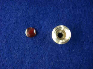
pivots) and to show this as a general example. First photo shows the individual parts
comprising four pieces. First the chaton front and rear views to contain the ball race,
(the top two metal pieces), the ball race itself, (center lower row) and the plastic ring
and end cap to hide the ball race. If the arbor extends through the plate, an additional
ring substitutes for the end cap (as seen in the last photo). The second photo shows the
ball race inserted into the rear of the chaton. Then the ring is secured next to the ball
race. The fourth photo shows the chaton flipped around showing the front. One can just see
the ball race recessed within. The fifth photo show the completed chaton. In the last
photo the arbor extends through the plate so a ring is used on both sides in lieu of an
end cap. The plastic is made of the same material used in automotive tail lights and so it
is the most durable we could find for strength and UV resistance.


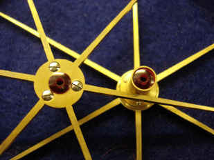
These two photos show a conventional jeweled chaton, a far simpler arrangement than
those containing a ball race. Jeweled pivots whether in chatons or without will be used in
the remaining two-thirds of all pivots (about 420). These are basically all pivots that
rotate less than one revolution per hour and are lightly loaded. The fly fans are an
exception to this rule, they use jeweled bearings but do rotate rapidly. These areas
command special visual attention and so real jeweled bearings were needed. The smallest
pivots will be of the plain jeweled variety. For example, most of the 200 or so pivots in
the grand orrery will be of this variety. The jewels are held in place by friction fit.
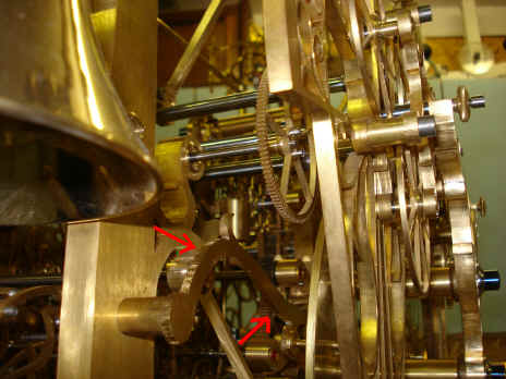
These photos show the positioning of the wooden mockup for the curvilinear
frames that will hold the idler wheels which will make up the strike snail transfer train
(see red arrows). As shown in last month's installment, this train of wheels acts to
transfer the once per hour rotation from the time train on the right hand side of the
movement to the strike train on the far left (as seen from the rear) a distance of about
20" (51cm).
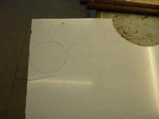
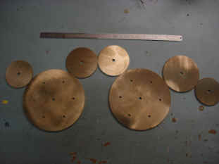

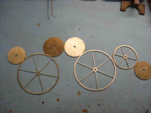


B now begins the fabrication of the idler wheel set. First the blanks are
cut from the brass sheet. The third and fourth photographs show the scribing jig he uses
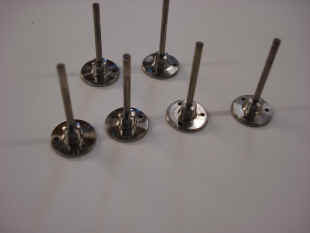
to lay out the beautifully thin spokes created throughout this project. The fifth photo
shows the single-ended posts that will attach from only one end to the idler wheel frame,
also known as 'dumb arbors'. These arbors do not rotate, but the wheels are free to rotate
upon the fixed arbor. There will be a pin at the end of each arbor to secure the wheel
upon it. Next are photos of the completed, jeweled wheels. Notice that each wheel has a
pair of pivot jewels.
The wheels are now positioned in their proper places upon the pair of
rough brass plates that will later be shaped into the curvilinear idler wheel frames.
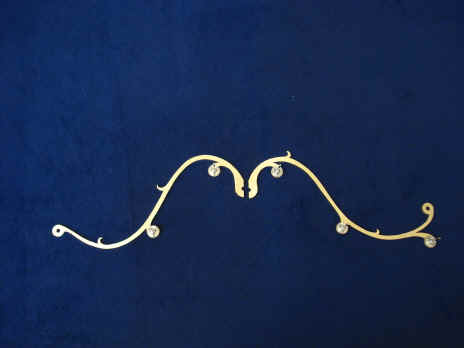

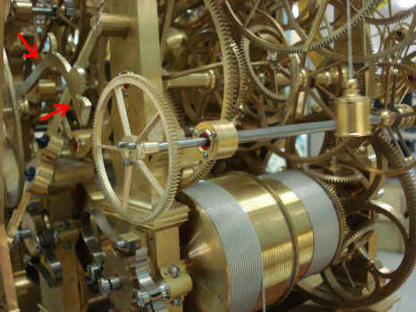
Shown above are the completed pair of idler wheel frames. These needed to
be in a split configuration since the wheels will be positioned through the pendulum
balances, in other words in the area encompassed by the vertical balance frame and
the diagonal bracing struts. Therefor, it's necessary for these wheels to be easily
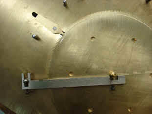
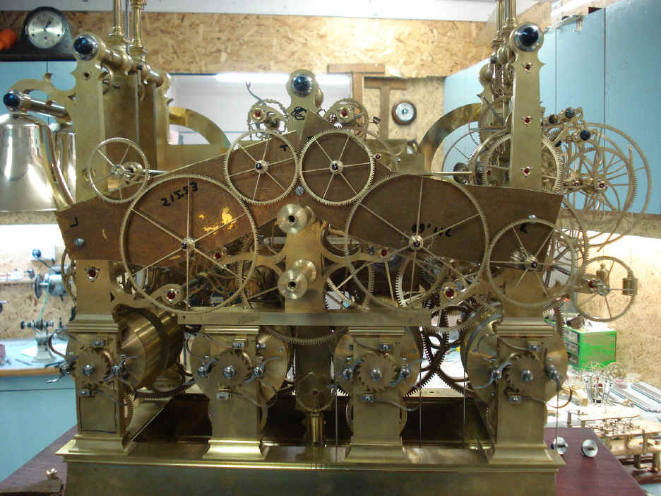
disassembled so the balances can be installed or removed. Next photo shows the wheels
mounted to those frames. Can you discern them within the movement shown in the photo
below?

Are you having a difficult time doing so? I hope so. Yes this idler wheel
system does play a bit of 'hide and seek' as shown here. But that is the whole idea of
this project, to pack in as much as is feasible into one incredible machine. To leave you
lost in a maze of amazement.