|
Debugging continues, the case is delivered - September 2021 This month we take care of final arrangements for the case, the glass hole measurements for the keyways as well as getting the proper height measurements for the final custom table that is currently on order.
The case arrives with the maker Fred Widman and his wife, Donna. It is made of a sturdy inner brass skeletal framing in which each glass pane can be inserted and locked into place thus allowing one to have access to the entire machine for purposes of demonstration, maintenance or cleaning of the glass. Each pane is glazed in brass surround and individually removable; the case has 321 parts and weighs in at 116 lbs., about half the weight of the entire clock, and is 16.1 cubic feet. This is why once the case is in place it will never be removed and has to have each pane removable. Theoretically once all the glass is removed two men could very carefully lift off the skeleton which is about 50 lbs. But it is risky. My plan is to remove the four bottom corner screws and then place the bottom rectangle of the case in place. Assemble and test the clock and then put the upper inner skeleton back on, screw it down and put in the glass. The table top dimensions are correct but the final table will stand about 7" taller. The table shown here is merely a temporary one. The actual design, far more sturdy, is shown below.
This illustration shows the positions of the major dial work.
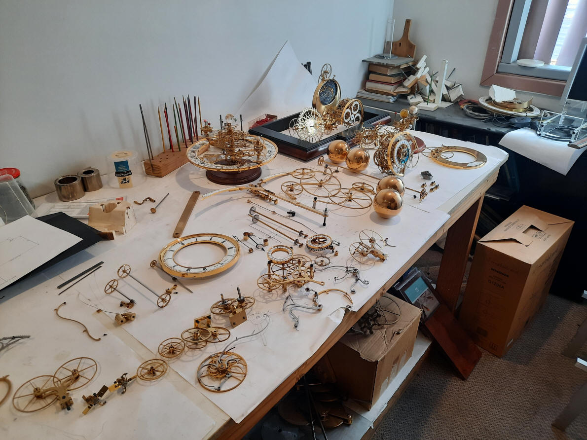
The dials are cut out and positioned where they will appear near the glass. Notice the center post in the middle and is more clearly shown in the photo below.
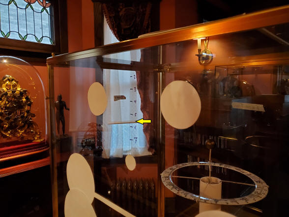
The post represents the height of the orrery and the ring the diameter of the orrery dial, first photo. This dial is, in fact a enamel dial that was replaced when we eventually moved on from a monochrome to polychrome format for the detailing and zodiacal figures. It is the correct size and so was useful in helping to determine the proper height of the custom table top. The second photo shows a paper line connecting the two upper paper dials taped on the glass and is the height where the orrery dial table is located.
There is a compromise that has to be made between having the table high enough to put all the dial work and mechanism near a favorable view and having the orrery dial rim just below eye-level so one can see all the planetary work. Generally skeleton clocks are displayed a bit lower than cased clocks as having an upper three-quarter view shows off the mechanism better. This is especially true in such a complex machine. The table was raised on temporary blocks until the right angle achieved at a height of 35.5" That angle is shown by the yellow arrow. Note the one inch markers used as a gauge to judge the differing angle relative to height.
This photo shows nearly the anticipated eye-level and how the clock will look on the final table, it will be about an inch higher than what it seems here. What is nice about the making of the custom table, is the fact that if the clock is found eventually to be too low, one can always fit four wood risers to the current table legs.
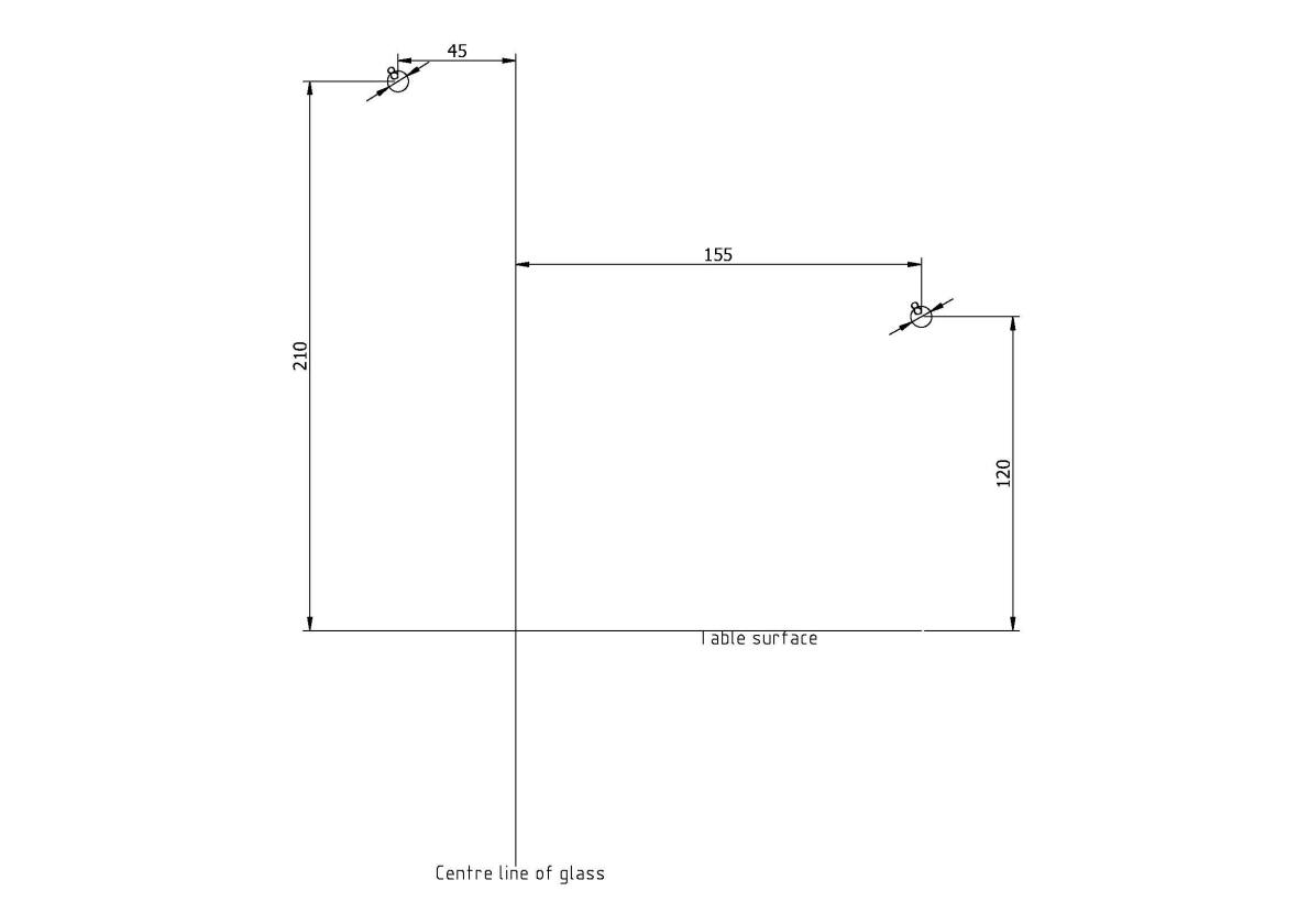
This illustration is the hole diagram for the front glass showing where the the keyways are to be located. Each pane is made of 1/8", or what is commonly known as double-strength glass. Each pane is framed in brass channel with associated screws, corner, and longitudinal stripping hardware. The front pane assembly weighs in at 16 lbs. and so for normal winding and demonstration purposes it is better not to remove it. There are a total of ten holes shown, but we will be only using nine keyways.
Here we see the holes drilled in the temporary plastic case, notice how even temporary holes have a brass ring for the trim! By the way one small bug found was when upon reassembly the equation of time sun was hung up on the hour hand as seen in the pictures above and below.
Same attention to detail on the holes here.
This illustration show right side pane with two holes for tool access, one to activate the pull/repeat chain and another to allow the operator to stop or start the pendulums.
The eleven keys ways for the front and right-hand side glass
Buchanan works on a bug (more like a tarantula!) that was discovered from a video made last month
It looks like the problem is at the axial area of the dual Wagner remontoire, unfortunately about as deep within the time train as one would care to get.
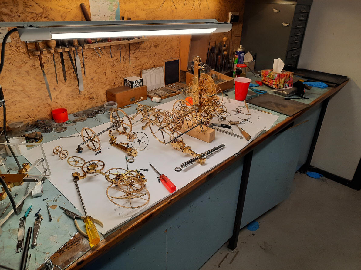
This photo above shows how much has to be removed to get to the stage of the
photo below, that is to get to where the celestial train can be removed.
Many of the complications mounted to the time and strike trains must also be
removed. The celestial train is the center and most complex of the three
main modules and it has to be remembered that the
trains are actually not fully
independently removable. The celestial train has to be removed before
one can remove either the time or strike train modules from the flat bed
frame below. This is unfortunate as the
photo above demonstrates since many parts that have nothing to do with the
two trains on either side must be removed to get the center celestial train
out.
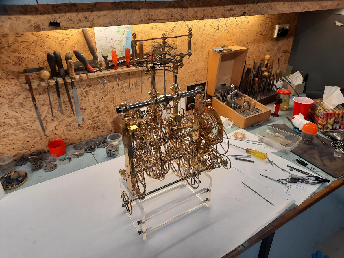
The center celestial train is now ready for removal after all the parts on the prior photo have been removed.
The celestial and time trains are now removed; leaving the quarter and hour trains.
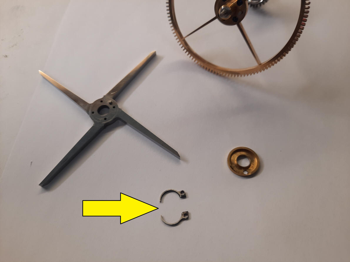
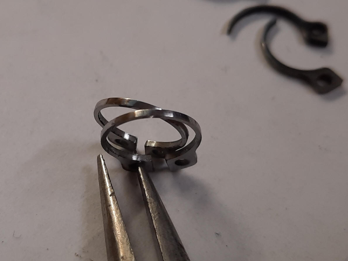
This where the problem was, a "C" spring had broken in half. Above is a the four-armed remontoire release cam. There is an identical one in the other Wagner remontoire and that one too will be replaced. It appears that a fatigue crack may have been in the metal or formed during fabrication.
The new fabricated and polished "C" springs finished.
This is the extent that the time train itself had to be dismantled to get at the area where the broken spring was.
The time train is now reassembled and ready for insertion into the machine.
The machine is back together. Please, no more bugs! |


![]()
![]()
![]()