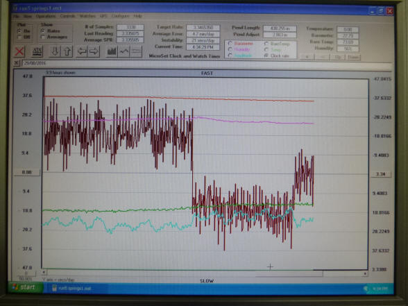
Here are two screen shots of the
first spring adjustment tests. The first rate of gaining 18.8sec/day was
with the springs stretched as far as possible. The second step was with the
springs relaxed by 1mm on both vernier scales
which gave us a losing rate of18.8sec/day. The
scale was set at a random position, so Buchanan
adjusted the graph to position the two rates as seen
in the first screen shot photo. So
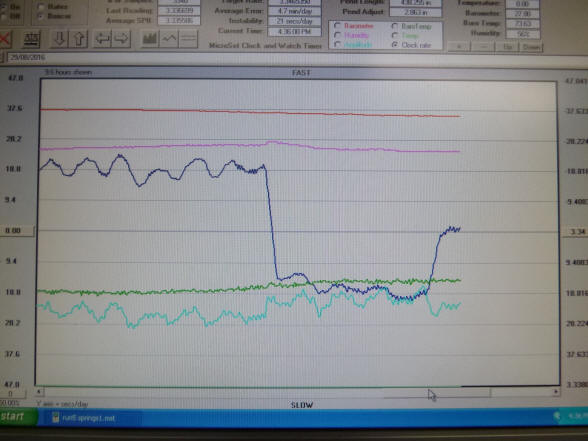
to get a theoretically correct rate he should
halve the adjustment he had just made. This
required a tensioning of the springs by 1/2mm. He then made the adjustment
and the new rate is as seen in the next screen shot photo.
So one mm release of the springs gives us 37.6sec day change.So one division on the vernier
will give us a change of 3.6 sec/day or 26.3 sec/week, and 1mm adjustment
will give us a 4.38 minute/week change This is with springs that give us a1.32 instead of a 2 second tick This is a reasonable
adjustment for rating the clock when it is running Next we
will see what it does to the isochronism. Unfortunately the construction of
the clock is such, that, we have in reality, about
4mm total adjustment. Hedoesn't think that it will make
that much difference to the isochronism, as he
agrees with what Mr. Drumheller wrote below,
that most of the error comes from the escapement.
Mr. Drumheller wrote:If we ignore the amplitude change in your
plots, you’ve just shown that simultaneously stretching all of the springs
by 1 mm increases their average stiffness by 0.04%. This seems to be a neat
way to fine adjust the rate of the clock. Now you should note that as the
balances swing two of springs are stretched an additional amount while the
other two contract. Thus the stiffness of two of the springs undergoes an
additional increase while the other two decrease. I suspect the net change
due to the swing will add to zero. That suggests the spring nonlinearity
you’ve just measured will not affect the isochronism.
It will be interesting to see just how temperature
stable this alloy is. The Harrison balance is interesting in that its beat
time is only sensitive to the change in stiffness of the spring. It is not
sensitive to the thermal expansion of the balances because both the balance
inertia and the restoring torque change proportionally so as to offset one
another and not affect the rate. Your test data may yield the most accurate
measurement of the temperature stability of this alloy that has even been
made.
Buchanan replies:You say: The Harrison balance is interesting in that its
beat time is only sensitive to the change in stiffness of the spring. It is
not sensitive to the thermal expansion of the balances because both the
balance inertia and the restoring torque change proportionally so as to
offset one another and not affect the rate.” Is this because the
point, where the spring is attached, moves away from the center
of the balance, so the spring has more ‘leverage’ to overcome the extra
inertia due the weights also moving away from the center of the balance.
Would this make the ratio between the distance from the center of the
balance to the spring attachment point and the distance from the center of
the balance to the center of mass critical. If this could be made
adjustable then could one ‘tune’ the balance to compensate for any residual
temperature error?
Mr. Drumheller replies:
Yeah! Frankly, I’ve noticed that you seem to have a knack for this kind of
stuff! There’s a few additional tricks I’ve had to add to this idea, but I’m
building it as we speak to see if it compensates my replica.
Now Buchanan has received the Elinvar-type wire. It is
actually
Ni-Span-C® alloy 902.a nickel-iron-chromium-titanium alloy made precipitation (42%, 47%,
±5.25%, ±2.5% plus several other trace elements), hardenable by additions of
aluminum and titanium. The titanium content also helps provide a
controllable thermoelastic coefficient, which is the alloy's outstanding
characteristic. The alloy can be processed to have a constant modulus of
elasticity at temperatures from -50°F to 150°F (-45 to 65°C). That makes it
ideal in the use of precision springs and is similar to the alloy Elinvar
used in watch balance hair springs, and is exactly what is needed for this
application giving the pendulums isochronism.
The conversation below refers to the data sheet that came with the
wire.
Buchanan
writes:The heat treatment looks interesting. I have attached a data sheet
on Ni-Span-C if you read it you will be as much of a Ni-Span-C expert as I am!
I aim to carry out tests on extension/force, as I did on the original
springs, but at different temperatures, on both carbon steel springs and
Ni-Span-C springs. Mr, Drumheller, would you know what force change per
degree I would expect. I understand principals, but my maths is poor as when
at school I had bad attitude as well as a bad teacher in a critical year.Buchanan
is funny!
Mr. Drumheller relies:The temperature error of my replica is about dt = 7.3 s per day per
deg F. There are t = 86400 s per day. Thus the ratio dt/t = 7.3/86400 =
.0000844 = 84e-6 /deg F.
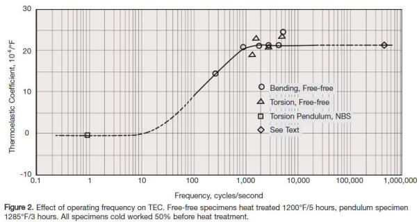
The thermo elastic coefficient in the PDF article is defined to be
dE / E, which is the change in the Elastic Modulus divided by the Elastic
Modulus itself. In our clocks we need to know the change in the Shear
Modulus dG divided by the Shear Modulus G itself. In Figure 2 they mix the
data for both these parameters together. The bending tests measure dE/E and
the torsion tests measure dG/G. I’m not sure they understand this issue.
For our clocks I have derived the very interesting result that dG/G
= 2 x dt/t. Thus based on the value of the temperature error that I have
measured the thermo elastic coefficient for the wire I used in the replica
is dG/G = 168 e-6. Notice that this value is similar to the larger values
that they have seen in many of the iron-nickel alloys shown in Figure 1.
Figure 2 indicates that you should see values of dG/G that are about 10 to
100 times smaller. That corresponds to temperature errors in your clock of
0.73 s per day per deg F to 73 milliseconds per day per deg F. The lower
values that they report are obtained from a torsional pendulum test. If the
wire in that test was subjected to a twisting oscillation of 1 Hz, that
would be very similar to the twisting action in your clock springs because
indeed the wire in a helical spring is twisted and not bent.
Figure 1 and Figure 2.
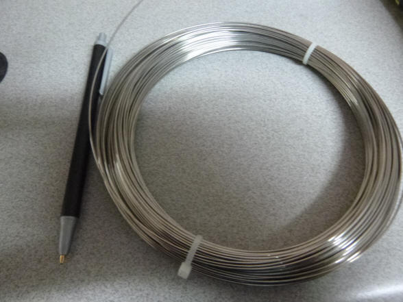
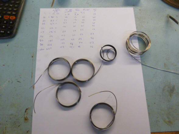
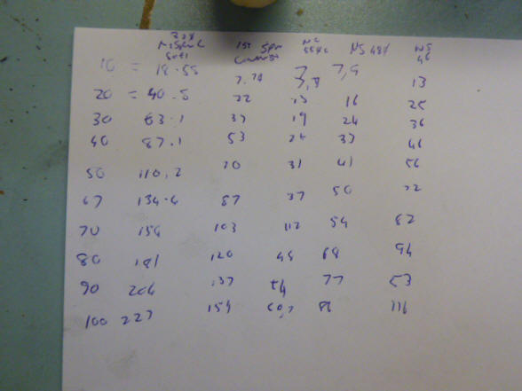
The Ni-Span wire as
received and Buchanan begins trialling springs. Buchanan writes: I
have been trialling springs. The paper shows the tension readings
for each diameter or material. I have installed the last test spring. The
1mm Ni-Span-C is rather too stiff so I have to have a 1.85 inch diameter
spring to get a 4.08 second beat. These interfere with the centre adjusters
so I removed them and fitted a wire link between the springs. The springs
have become rather heavy now, I will send a video of the clock running and
you will see the sag when the springs are relaxed. The timer is running and
as soon as the clock is stabilised I will up the temperature and see what
happens.
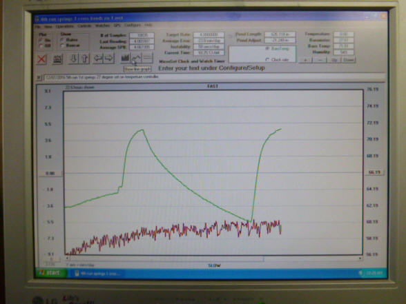
The last photo shows a fairly steady rate over a
temperature swing of nearly ten degrees. It looks like the invar springs are
going to go a long way towards correcting for temperature error. I asked
about the error introduced by the physical changes to the pendulum balances,
which is as temperature increases will tend to become longer. With the
Ni-Span springs in place and assuming the stiffness of the springs do not
change, the small additional restorative forces (torque) of the springs due
to the fact that the distance from where they are connected to the top of
the pendulum to where they are anchored to the vernier on the clock frame is
slightly further apart as the pendulums expand, will compensate for the
thermal expansion of the pendulums. Imagine the joy Harrison would have had
if he could have eliminated the complicated, multiple grid iron compensation
system on H1 with the simple substitution of a nifty set of Ni-Span springs!
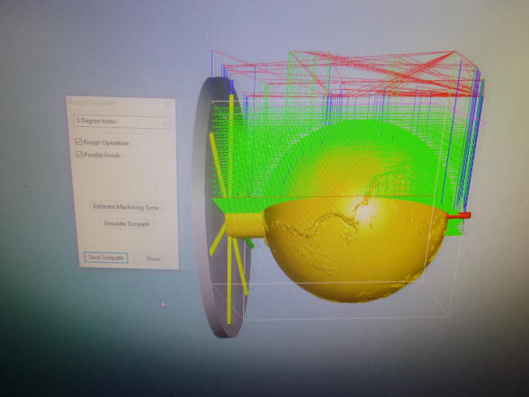
Buchanan now turns to the fabrication of the Earth globe in the
tellurion.
We explored a number of
designs for the Earth globe. This besides the Sun is the largest planetary
body represented in any the celestial displays, (we still have an orrery to
complete). So it will command special attention. I wanted it to be
immediately recognizable as the Earth so a natural stone analogy would not
work. There are globes commercially made from stone mosaic but these need to
be much larger than our 1.3” (3 cm) diameter to get the detail necessary. We
will, however, be using semiprecious stone spheres for the remaining
planetary bodies as well as the Sun in both the tellurion and future orrery.
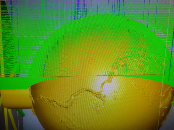
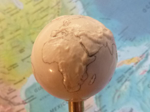
The current Earth, Sun and other planets as seen up to this point are still
mockups. These two photos show the Earth globe modeled on the computer,
the South American Andes mountain range is clearly visible.
I wanted the Earth globe to have a special look. I have always
admired the quality of walrus and ivory scrimshaw artwork. Scrimshaw allows
the artist to create a very detailed design on the bone surface and when
dyed with black tea or ink creates a beautiful effect. Since ivory
importation has been banned in many countries as well as this machine’s
ultimate destination, we had to use an alternate material. Walrus was the
first choice, but it was too difficult to find a piece of walrus tusk large
enough to obtain the piece we needed. One must remember that these are
natural materials and often have cracks and other imperfections around the
perimeter reaching inward. One needs a large cross section of material to
get a perfect area at the heart of the tusk to obtain a flawless piece. This
is especially true with Mammoth ivory since it is very old and so is prone to
greater cracking. Any imperfections would be picked up in the dying process
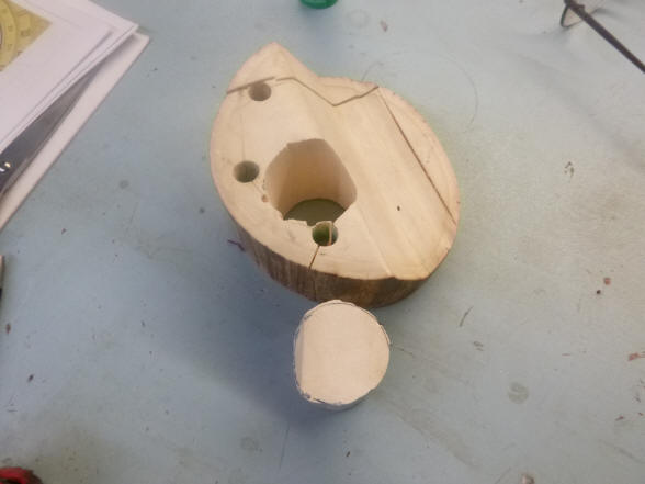
after the scrimshaw had been completed. The first photo shows the Mammoth
ivory piece we used. One can see how large it needed to be to get the
perfect rough blank. Mammoth also has a nice patina with natural growth
markings, just the look I wanted. There is enough material left over for us
to use elsewhere for winding handles. Another feature that Mammoth afforded
was the ability to create land features on the globe. From the beginning we
decided against political boundaries. First these are simply too complicated
for a globe of this size and second these will change throughout the life of
the machine. But we could outline the land masses as well as adding
longitude and latitude lines. This material also allows one to carve the
piece in relief to illustrate the various continental mountain ranges;
another departure from the standard smooth Earth globe found on other
tellurians, especially at this scale. Mammoth also yields easily to the
cutting tool and is not brittle, so an accurate model could be produced.
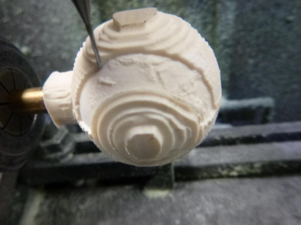
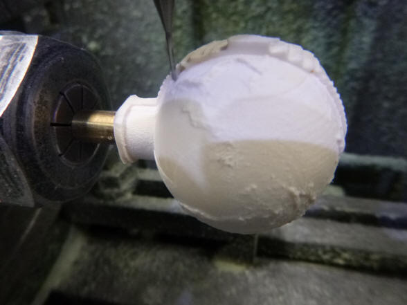
The ivory blank is mounted into the mill and
begins to take shape. Here again is one of the few but absolutely necessary
areas where a computer designed and manufactured process is employed. If we
had gone with a smooth globe a normal machining process could have been
used. But to get the continental land mass reliefs coupled with perfect
spherical areas for the oceans would have been very difficult to achieve
otherwise. Buchanan had practiced on several plastic test
pieces prior to the final material. The tool will travel nearly 300 meters
to complete the job. One other advantage to this material is the fact that it
is soft enough that cutting fluid is not needed to cool the tool thus
avoiding the contamination that would happen if one used stone where the
fluid would infiltrate into the rough-cut surfaces. Still the machining took
two days.
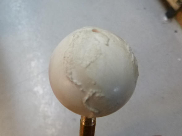
The video below shows the early steps in the
machining process. After the
machining process is complete, the machine tool marks had to be smoothed out
by hand. The
entire globe took an additional two days to be finished off and polished by hand.
Buchanan writes: I will just take a quick course on scrimshaw and the globe should be
finished by lunch time. The machining went well. I am now removing all
machine ridges with gravers. Then I will outline the continents and then ink
the outlines. Then onto the lathe with the ball turning attachment and
protractors I will add the latitude and longitude lines. Have you thought
about the spacing of the degree lines? I thought of 24 longitude lines, each
representing an hour. Then for latitude something equally spaced with darker
lines for the equator, topics and arctic circle. Also darker for Greenwich
meridian. Also thought of two solid gold pins (Major Expense) for Chicago
and Moss vale where it was made. These would be 12 thou in diameter. Real
small, just a speck.
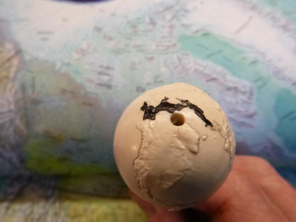
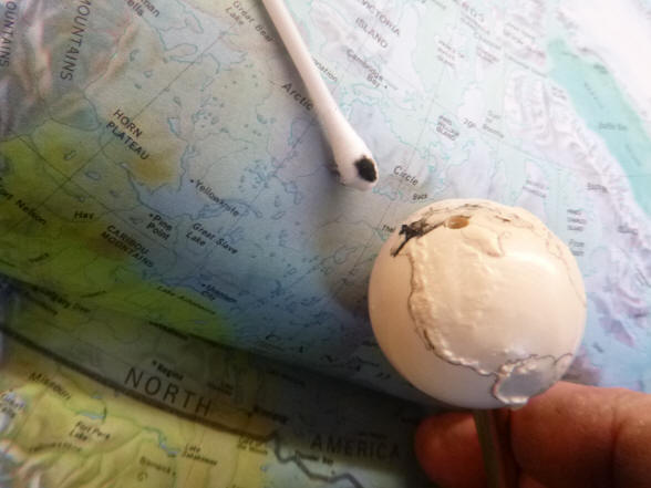
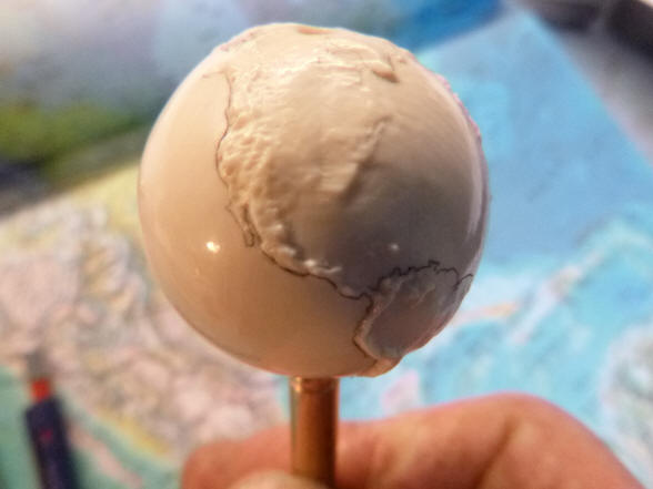
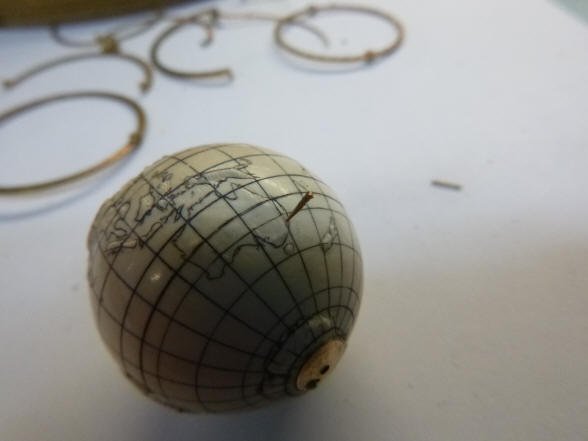
The globe surface with
its final polish and the beginnings of the continental outlines inked in.
The process is slow, first the outline in pencil, then engrave, then the ink
then repeat for another one-half inch of coast line.
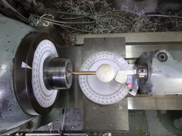
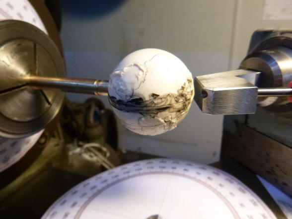
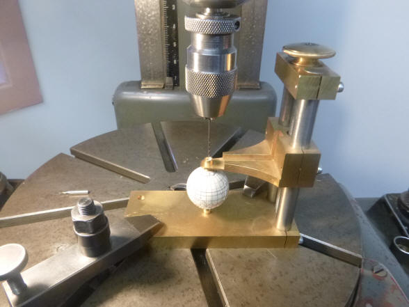
These two photos show the scrimshaw process for cutting the
latitude and longitude lines. Notice the two protractor scales attached to
the tooling used to rotate the globe and move the cutter. This gives an
accurate positioning of both the globe and cutter in the X-Y axis for
perfectly accurate lines.
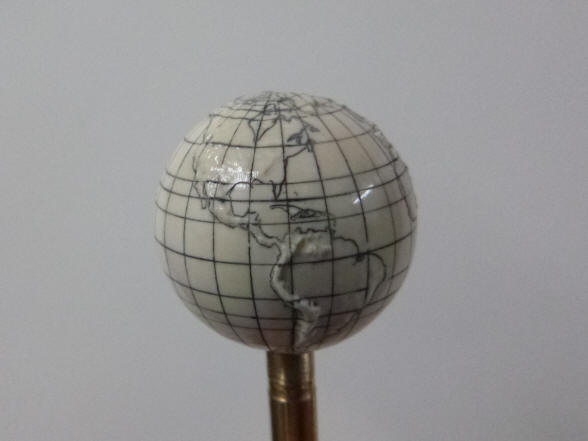
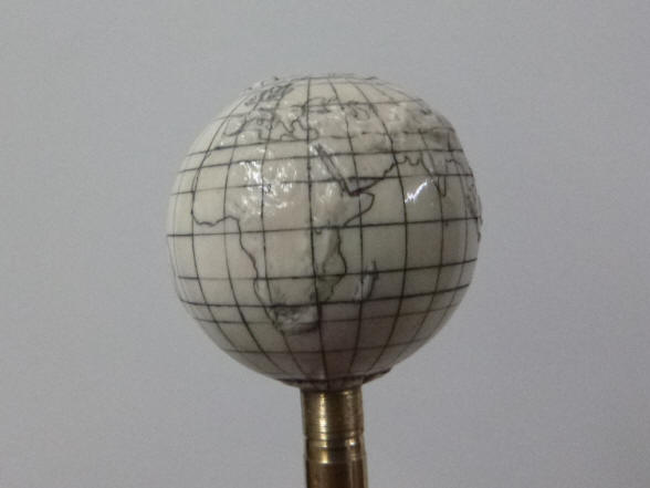
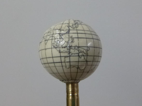
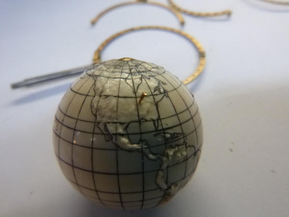
The finished globe is
ready for installation into the tellurion. We decided to go with the
standard twenty-four for latitude lines, but Buchanan, wisely, chose not to put
all of the longitude lines, it would have been too distracting from the
geography depicted on the globe’s surface.
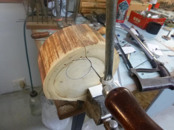
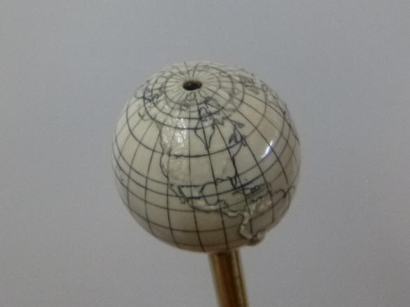
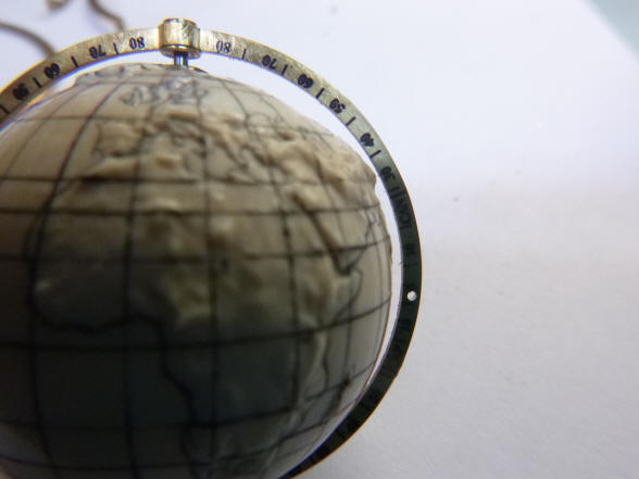
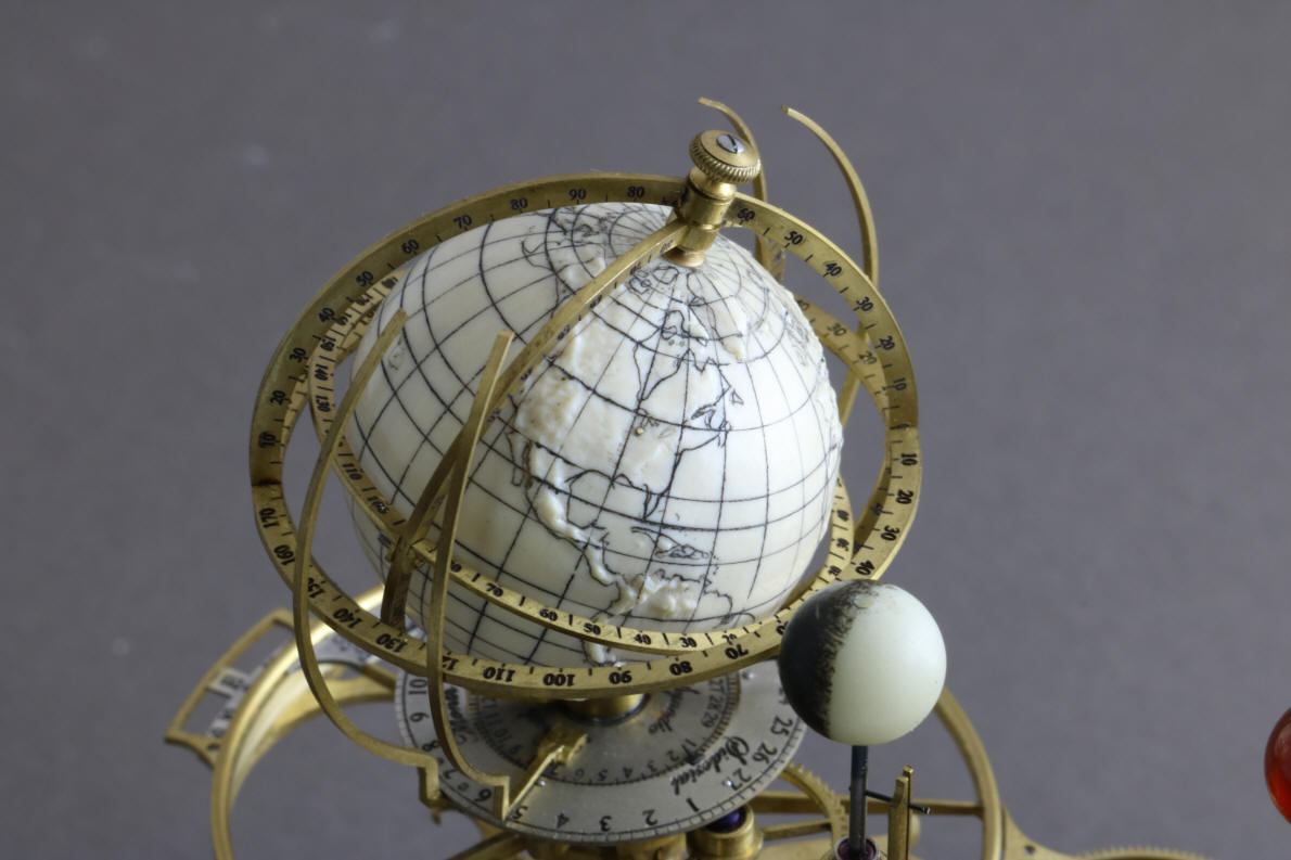
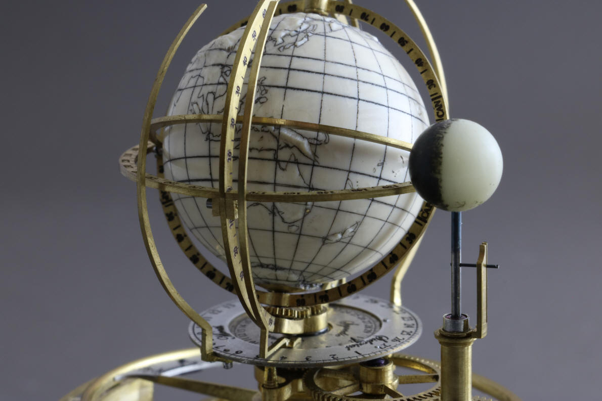
In the first photo
Buchanan drills out the brass mount used up to this point to hold the globe
during the prior machining processes. Next is the initial fitting of the
globe within the globe longitude ring. Notice how Mt. Everest barely clears
the ring! This photo really shows off the exaggerated topography of the
globe. Here is where the use of computer aided design and machining produced
a superior result, one that would have been very difficult to reproduce
accurately by hand and sets this globe apart from others.
Buchanan now inserts a gold speck at the
location of Chicago, USA and Moss Vale, Australia. If one looks closely
at the North American continent there is something missing and very
important to the city of Chicago, the Great Lakes. Chicago sits astride Lake
Michigan the fifth largest body of fresh water in the world.
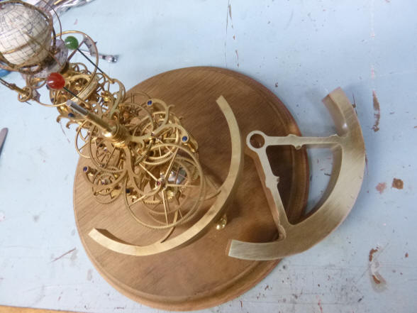
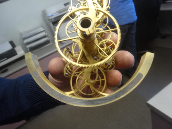
The first photo shows a
new, heavier counterbalance that was needed because the Mammoth ivory is
considerably heavier than the aluminum mockup globe. To reduce this heavier
look a lead insert within the sickle structure was needed. In the second
photo the final profile of the sickle is much reduced. Note how neat and
tidy the lead insert is.
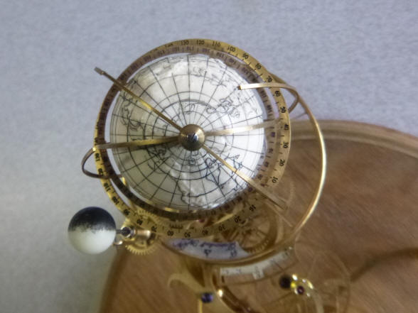
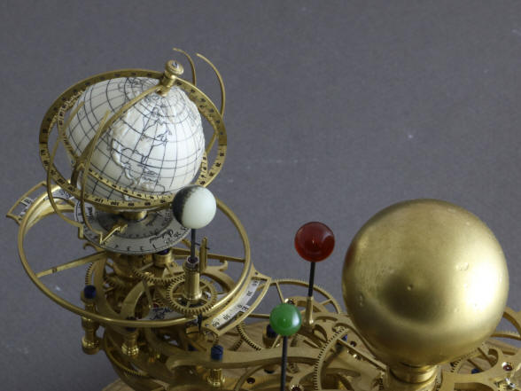
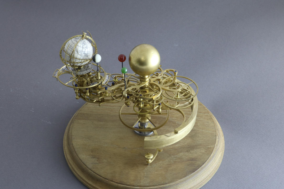
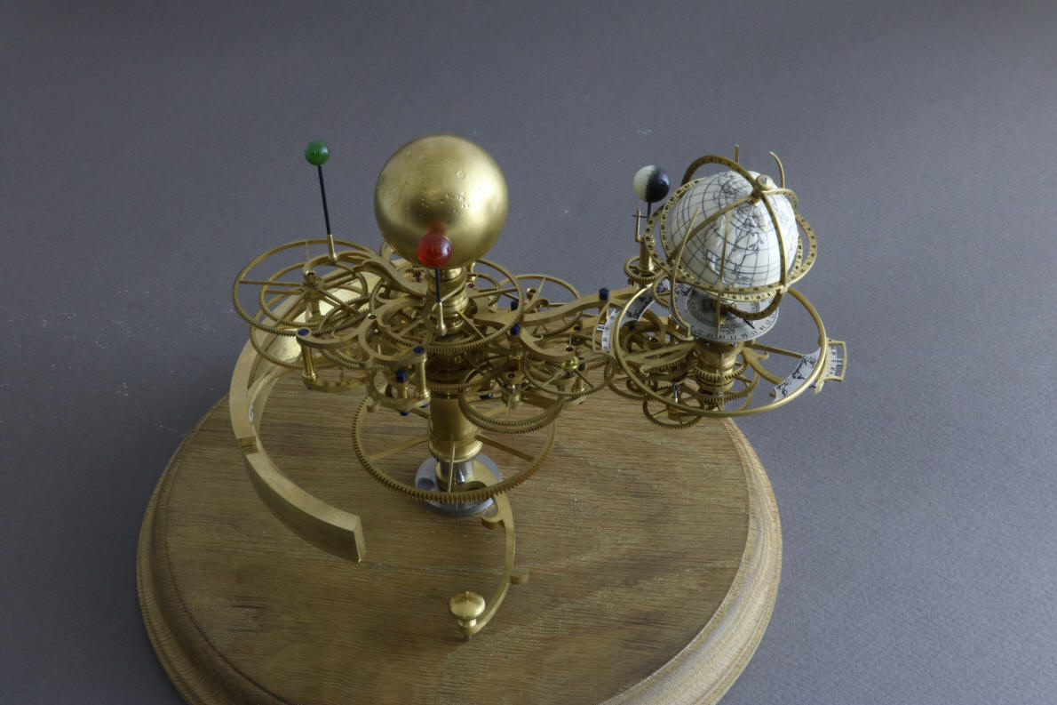
Look, the great lakes have appeared and Chicago now has its beautiful
lakefront! Also note the pair of sun and moon horizon
arc-markers as well as the detail engraving on the longitude, latitude and
ecliptic rings. Below reside the synodic and sidereal month dials, and in
the background the eclipse dials. As you look over the remaining photos
note the incredible detail, complexity and the numerous (nine) complications
that are incorporated into these three inches (7 cm) of volume.
These mechanical, design and artistic skills are repeated hundreds of times
within the six cubic feet ( 0.16 cubic meter) volume of the entire machine.
The gold pin for Moss
Vale can be seen just below the lower horizontal ring.