|
Continue Sun / Moon rise set, dial output drive assemblies, sun drive, hours of daylight and nighttime sub-dials - July 2017 This month Buchanan continues with the output drive section of the sun/ moon rise-set module responsible for the sun revolution, sun horizon shutters and moon sphere revolution and rotation.
We had a clearance
problem in the area where four bearings are needed to support the sun and
moon hands. These photos show a grinding machine where the four ball bearing
supports for the sun and moon output hands were had their widths ground down
by 37.5%.
The difference between
the original and altered profiles is shown. The pair of tweezers in the last
photo shows how small these bearing are.
These first photo shows
the old shaft still inserted into the drive mechanism with the new one on
the table note that there is an inner sleeve on that part. The entire part
will then fit into where the old one is currently located giving two
separate rotating shafts where before there was one. Special care will have
to be taken to make sure there is maximum shielding of the bearing since the
original factory shielding was ground away.
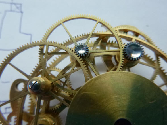
A while back I had asked Buchanan to machine the large flat areas of the wheel pinion heads. The photo shows how those areas were nicely dished. Buchanan made a new brass disc to replace the original bearing retainer which showed up a clearance issue and a mechanical weakness so he had to remake it in stainless steel with strengthened dimensions. This is now complete. The second photo shows the original small ring, the brass ring and the stainless steel ring on the mechanism. It is very much oversized at this point and will later be skeletonized.
The
first photo shows sparking a square hole in one of the transfer pinions and
then depthing the pinion.
Next
the bearing seat is machined and the pinion positioned.
All
that needs to be done now is to drill and tap the holes for the screws that
hold the brass bearing cap and the transfer drive will be operational; then
cut away the shutter bosses for clearance for the centre dial pillars and
the transfer pinion.
The transfer drive for
the sun tube is nearing completion. The second two photos show a bit of
finishing through the polished dimple on the steel pinion as well as the
blued screw covering the empty square hole in the photo above it.
Earlier I had expressed
concern about the large steel disc and from this front and rear elevation
one can see it has largely disappeared.
Now Buchanan begins the
fabrication of the two small day night hours indicator dials. These photos
show the initial cutting out of the brass bar stock.
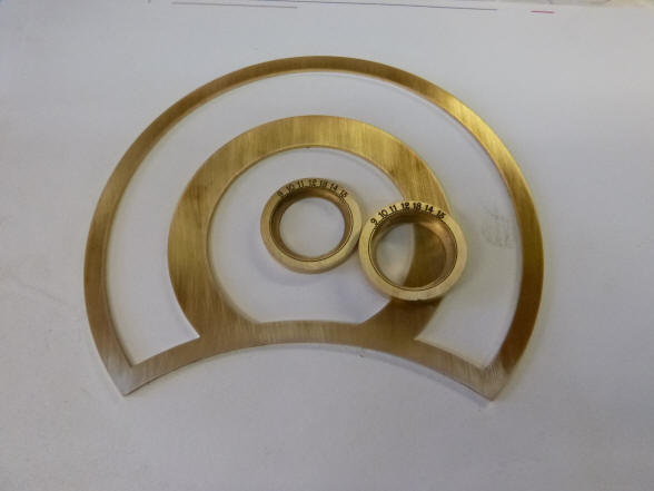
The engraving was
applied when the ring was still part of the bar stock and this piece is now
cut away. Next the dial ring is fully machined out of the bar stock. Later
this ring will be machined into a small sector encompassing only the numbers
and and a foot for mounting screws to the center hub.
The pair of dials, one
for day and one for night. The day dial will be silvered with black numerals
and the night a black background with white numerals.
Whew! Let's take a break and look at what we have on
the bench. This is an overview of the module
frame. Notice how it closely mirrors the calendar frame which will reside on
the clock directly to the left side of where this complication will be
positioned. This is another example of Buchanan’s efforts to create
continuity in design throughout the machine.
The dial ring being
turned in the lathe to its final shape.
The ring has been
machined down to a small sector which is mounted to the center hub. In the
next photo the second ring is mounted to second hub. One can just see the
cylindrical cannon tube below which will slide into the central hole shown
in the first photo.
One can see the
independent movement of the dials in these two photos. In the first photo
both dials are moved to be adjacent to each other at the 10 o’clock
position; in the next photo at 3 o’clock. Each dial will be controlled by
one of a pair of cams controlling the horizon shutters and indicate the
number of hours for daylight and nighttime.
The second photo shows
how the hands must tuck under the center wheel.
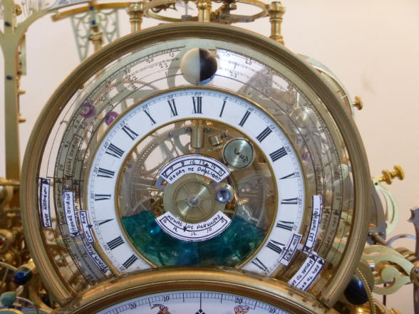
The drive assembly has come to a stage where the mockup dials can be attached to get a feel for how the presentation will look on the clock. However I see a problem with the mockup as is. The outer dial is obscuring everything behind it. That dial along with the inner Roman numeral dial and center hub combine to nearly hide everything behind the upper dial work. Every dial on this clock so far has been designed to minimize the footprint yet maximize the information content and legibility. We will explore a glass dial alternative with the information laser-etched on the inner surface.
The planisphere dial at the bottom is still a mockup piece.
I like this arrangement in the first photo much better. The entire appearance is lighter with the glass mockup than the right photo with the enamel dial mockup. The center length of day and night dial has also been changed to two sector dials, eliminating the solid center 'button'. I have some experience with glass clock dials and the legibility of the dial when finished is very good. The mockup as shown is a plastic sheet with hand drawn lettering and so does not look as good. Later we will see that the set of horizon shutter cams with a special design will show beautifully through the glass area in the upper left sector. |


![]()
![]()
![]()