|
Continue Sun / Moon rise set, begin dial hand drive assemblies - April 2017
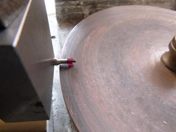
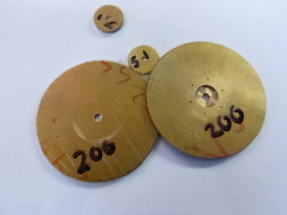
Two jewels had to be
custom cut to fit for the sun hand because the sector wheel tube that
carries it is not large enough to fit a standard size jewel. The first photo
shows a jewel on the lapping wheel to accomplish this. Next the two cut down
jewels compared to an unaltered diameter jewel, left.
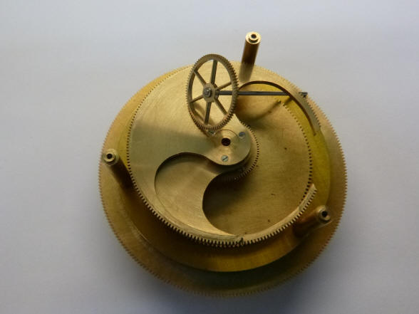
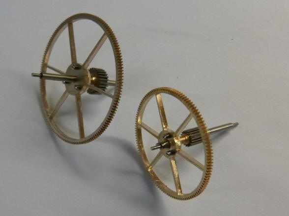
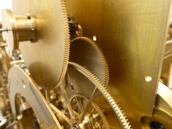
These two photos show
the two sector gears partially cut out which control the sun rise and set
shutters.
Buchanan writes: The drive to the sun hand is complete, including the setting clutch and spoking. Next is the three final arbours on the 1 year rise/set cam drive. This should be done by Friday I hope. I want to keep the sector wheels as much of a circle as possible, even if only 35 degrees of drive is required. Then we can make a good spoke design to accentuate them.
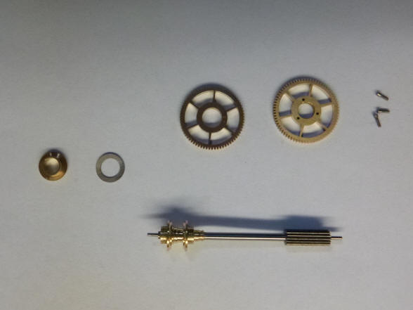
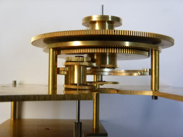
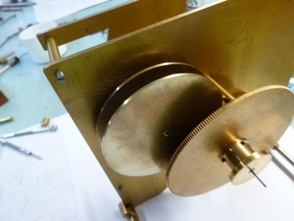
The first two photos are the sun hand drive, next the drive inserted into
the assembly and finally the two main plates for the sun / moon drives.
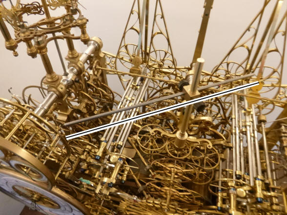
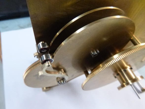
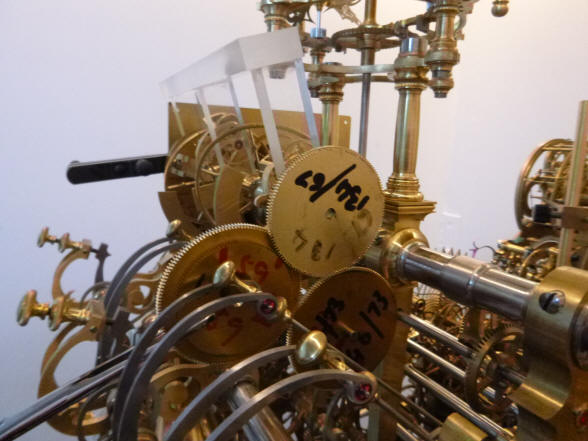
The first photo shows a
sweep arm that was installed where the vertical axis of the orrery is
located, see white parallel line. This used to be sure that no components
are created that will conflict with the diameter for that yet to be
completed component. This
device is clearly visible in the space between the calendar and the current
sun / moon assembly.
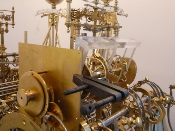
Further progress within
the sun / moon drive assembly. The second photo is the drive for the shutter
cams.
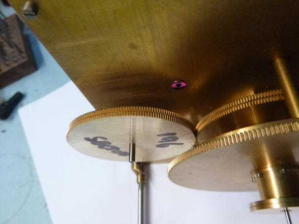
The blank cam pair is
fitted to the drive arbor. Next the wheels are beginning to fill out. There
are still another twelve wheels to be added as well as the moon.
The first photo shows
the sector gear pair, not yet cut into the sector shape, and the same arbor
that will also carry the cam follower arms on the blank space on the arbor.
Next is a view from the rear showing the mount for the dumb arbor that hold
the sector gears.
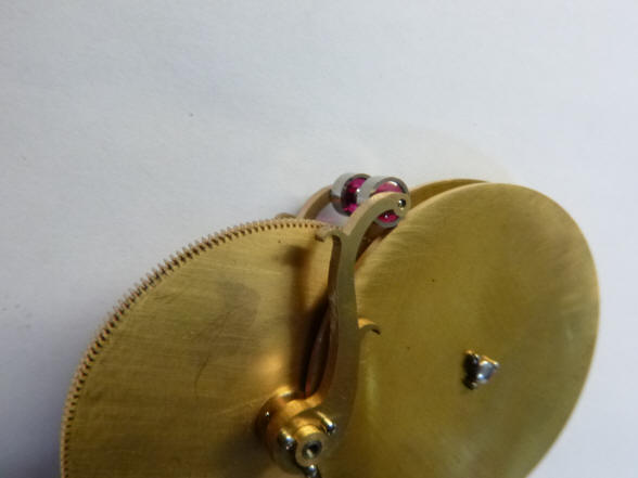
The cam followers are
now complete. Cam rollers are made from a pivot jewels as are all other
rollers within this project. This eliminates the need for oil. The last
photo shows this assembly in place on the clock.
Buchanan
writes:
I have the dumb arbour and the collet almost finished on the idler wheel.
Once I have this finished I can depth and mount the long arbour that takes
the drive to the back of the slant wheels. This means that I can then start
the frames for the slant wheels. The last photo shows
the rear plate stripped of the sun / moon drive work. Note the center quick
release mount attaching the entire assembly to the clock frame. The idler
drive wheel is in place.
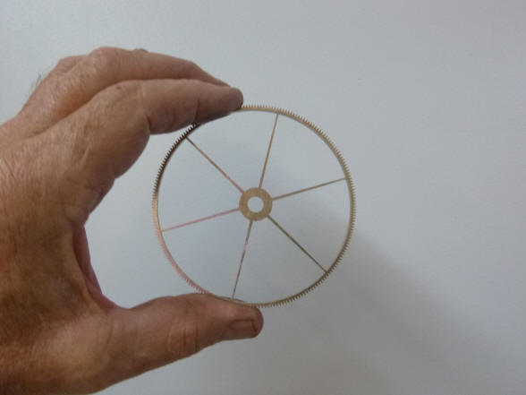
The input idler wheel.
This wheel carries the drive from the tellurian to the sun / moon assembly.
Notice the second, smaller wheel which was needed to introduce the correct
input into the moon anomaly differential set. A second wheel meshing with
the smaller wheel results in the correct counterclockwise movement of the
moon.
Buchanan writes:
I have the long arbour pitched now, it takes the drive to the back of the
slant wheels. This is one of the few arbours that are bare between the main
plates.
There are four more wheels to mount at the back of the slant wheels and two
wheels more in front of the slant wheel but behind the back plate.
I am going to have to make a jig to find the best position for the
slant wheel assembly. I need to hold it square to the frames but be able to
move it and spin it around to be able to fit it in the best possible place.
This is going to be fun!
Buchanan writes:
I recut 2 wheels, the large wheel that carries the gear train for the
rolling moon and the out feed from the
slant
wheel assembly. I also cut the 2 transfer wheels to bring the drive from the
slant wheel out feed to the front of the back plate. These 4 wheels bring
the drive from the slant wheels to the moon arm.
I had to reduce the size of the first two wheels just to fit them into the
space available. They are actually now the size I originally drew them. I
made them as large as I thought I possibly could but overestimated
somewhat. In this 4 gear train I must also include the moon setting clutch.
So my next operation is to decide where to place the centre line of the
slant wheel assembly. Then I can decide on the frame and pillar design. I
would like a single pillar but will have to see if that is possible, the
main back frame of the moon dial will have to support the slant wheel
assembly but I may be able to provide a rear support to stabilize the
slant wheel assembly when it is in the clock.
The
second photo shows the initial hand trial of where the anomaly differentials
will be located.
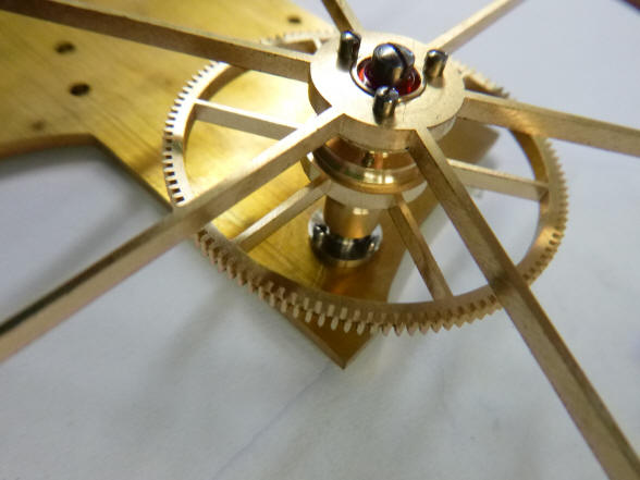
These two photos show the differential set clamped into place and the rear drive wheel blanks in place. Here one clearly sees that the differential set is driven from the rear and the corrections are the output at the front and is then delivered to the moon drive. The additional two wheel blanks to the left are those depicted as the recut wheels described above.
The
second photo shows the rear drive wheel blank removed to show the
differential set end-on.
|


![]()
![]()
![]()