|
Complete the reversible, perpetual 400 year calendar calculator module - February 2015
Shown here is the four
hundred year cam assembly. The four lobed Geneva cam will rotate once in 400
years in four 100 year increments.
The first photo shows a brass blank with holes being drilled for wheel pivots and fastening points. The blank has been made to copy the diameter of the rest of the perpetual calendar calculator so as to better ascertain the correct proportions for the frame that will be cut from this. Next the decorative upper frame is cut from that blank.
Next are two photos showing the layering of components both below and
above the frame.
Now
the main construction of the date mechanism
of the calculator
is finished. Note how small this is. Next the module is shown in the context
of the rest of the calendar mechanism.
These
photos show how the perpetual calendar module will look with the context of
the rest of the calendar work. It is located behind the date dial at the
apex of the calendar dial cluster. One can readily see why there is so much
space between the dial cluster and the rear plate. That space is needed for
the perpetual calendar module. The solid disk will later be fretted out.
The
three ‘surprise pieces’ are shown in the first photo. These were first
described in the October 2014 section of this project. The term ‘surprise
piece’ is a
phrase
first used in the 18th century in connection with pocket watches
that performed complex repeat functions in their strike work. Quarter and
minute repeat functions required separate, movable steps to add or subtract
from the profile of the snail work steps used to count the strokes of the
strike hammer. What these parts do is to add or subtract the number of
detents that are present to read the output for the date. The top piece is
controlled by three cams, each rotating once in 20, 100 and 400 years to
introduce or remove the 29th day in February that are exceptions
to the regular four year leap year cycle. The next two are controlled by the
normal four year leap cycle as well as the cam indicating the months having
30 and 31 days. Notice that we still continue our ‘bird motif’ even in these
very small parts. The extended beaks on the top and bottom pieces are not
necessary to their function. The next photo shows these pieces in place
within the module.
The
surprise pieces are now assembled. Even these small spacers have some
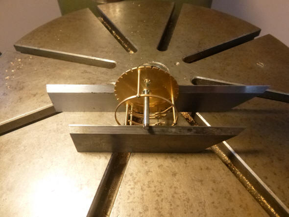
decorative turning. The perpetual module contains four independently
rotating disk-shaped platforms
numbered 1 through 4 as shown in the fourth photo. All platforms
contain some combination of wheels and cams. Each one will, as the finishing
progresses, be poised so as to minimize the amount of energy needed to
rotate them. The fifth photo shows the overall module cage on two parallel
knife edges used during the poising procedure. If this precaution were not
taken, then conceivably,
at some point in time all four rotating platforms could align where each has
its greatest imbalance resulting
in a
possible
stoppage.
Here
we have another example of
Buchanan's
tour d’ force
of his skeletonising techniques. The solid, crenulated date disk seen in
the prior segment is now fully fretted out. Any other
conventional
maker would have simply left a solid inner rim, thus saving a huge amount of
effort. But here he follows the crenulations exactly to produce a
magnificent and delicate undulating rim design no larger than a silver
Dollar coin, 1.5 inches, (3.5 cm) and is as thick as a thin piece of
cardboard. Also shown is the 30 or 31 day
cam
for the month; the first of
several oddly shaped cams.
The
first photo shows a
front view of the calculator and attached is what looks
like a chapter ring,
red arrow. This is the base to which, in fact, a
tiny chapter ring will
be fitted with the individual months of the year, second photo. The
engraving will later be cut into the final ring shape and silvered with the
lettering filled with dial wax.
One
can see how incredibly crisp the engraving is at this small scale.
Buchanan says that he sharpens his engraving
tools with diamond lap cutters. Then to be sure the spinning engraving tool
is set perfectly dead center in the lathe chuck he lets the tip touch nail
of his finger to feel for any shake. He readjusts the tool in the chuck
until all vibration is eliminated. This allows for maximum accuracy for the
engraving cut, as well as several small holes in his fingernails.
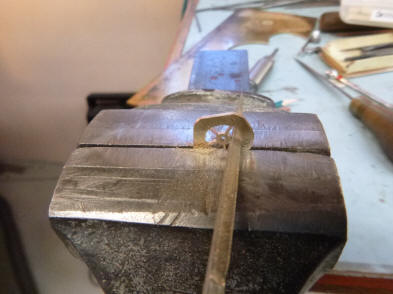
Next
is some of the hand filing used to shape the cams. The month chapter ring is
then installed. It seems a pity that the foot of the drive wheel cock has to
be mounted over the month of January,
red arrow, completely obscuring it. Later this
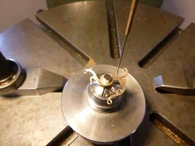
part of the ring will be completely cut away. Here we see Buchanan using a piece of clay to poise the one year cam along with the month chapter ring. The perpetual calendar module has four separate rotating assemblies and each must be individually poised. This prevents any problems that could arise should all four assemblies, if unbalanced align into a quadruple un-poised position. A situation that could occur every 400 or so years. Next the assembly is shown nearly poised.
The
twenty year cam is cut out on the piercing saw. The 400 hundred year cam
assembly is seen just to the right. Next the twenty year cam is installed in
the second photo just above the month chapter ring.
This
photo shows how petit this whole calculator really is.
Here
are the main components of the reversible 400 year perpetual calendar
calculator. The total comes in at a bit over 102 parts. The main components
are as follows: 1. Daily index wheel, this advances daily and is where the drive to the calculator begins
2.
One year cam, controls the duration of February in non leap years
3.
Ten year cam
4.
Twenty year cam
5.
One hundred year cam
6.
Four hundred year cam
7.
Twenty year chapter ring
8.
Month chapter ring
9.
Calculator frame assembly, partial
A.
Four hundred year drive assembly
The
S1 through S4 surprise pieces
described below operate in the open area of the rim at the 3 o’clock position on part #1, the daily index wheel
S1,
S2. Dual surprise pieces that are controlled by both the 100 and
400 year cams
S3.
Surprise piece for introduction of extra day in February in normal four year
leap cycle
S4.
Surprise piece for the introduction of the 31st day in the
appropriate months, excluding February
The
remaining parts are ancillary drive wheels, Geneva drives, fasteners and
support parts.
These photos give a
comparison in both weight and size of the calculator in relation to a wrist
watch. In the first photo the wrist watch movement comes in at 36.1 grams
with the calculator, second photo, weighing in at 29.7 grams, 1.047 ounces.
The completed
calculator. It looks a bit reminiscent of a skeletonized tourbillon
escapement model.
The first photo shows
the calendar parts to date and those parts including the perpetual calendar
module mounted behind the calendar dial cluster. That cluster is currently
still a wooden mockup.
Now we turn back to the
rest of the calendar work. The first photo shows the hand filing of the
detents which have again been shaped into the characteristic bird analogue
used throughout this project. The five detents will be used to read the output of both the calculator
and balance of the dials are shown in the next three photos.
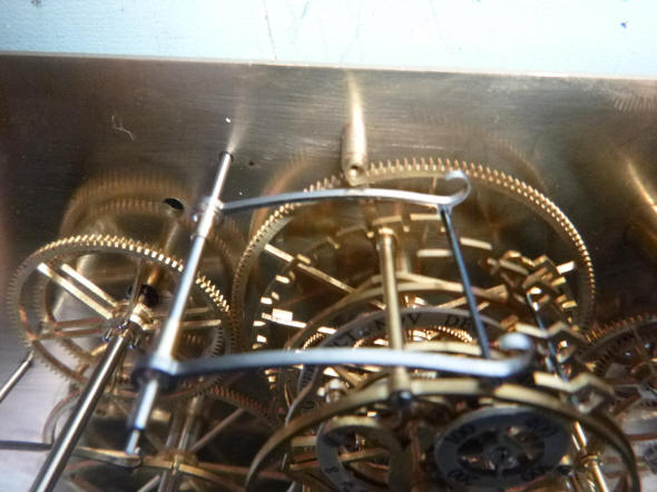
Those detents are now in place (red arrows).
The first photo
illustrates a set of paired detents used to read the data from the calendar module. There is
actually only one detent, the one in the background which reads the
crenellated daily index wheel. It is connected through a wire to another
nearly identical looking piece in the foreground which only serves to secure
the other end of that wire. Both parts are fixed to and pivot upon their
arbor on the left. The wire is necessary as there are three separate cams
positioned across the width of this module that will actuate the rear detent
through contact with that wire at various times throughout the calculator’s
400 year cycle to either engage the crenulated wheel or keep
the wire raised so one or more teeth on this cam are skipped. The last photo shows one of the bird-analogue detents
located into the leap year wheel groove. |


 \
\


![]()
![]()
![]()