|
Begin Sun/Moon rise/set complication, the variable differentials - January 2017
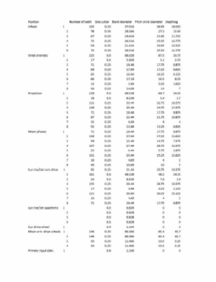
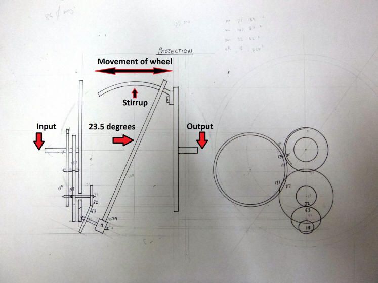
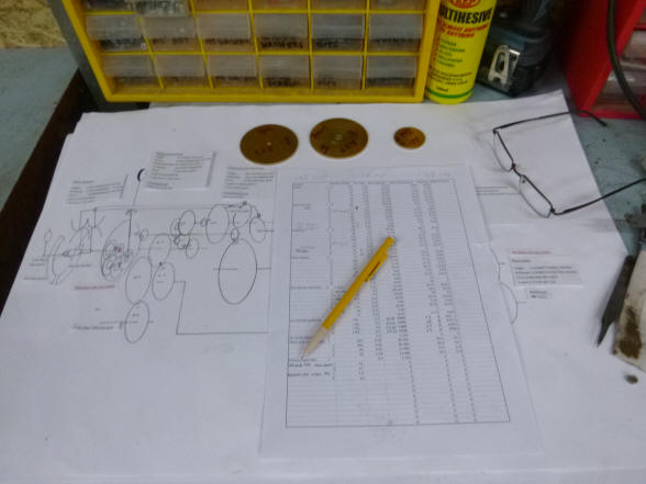
This month begins the fabrication of the Sun and Moon rise and set complication. The first diagram shows the wheel chart specification sheet. This complication has a total of 54 wheels. Next is the scale drawing of one of a pair of Janvier style differentials, this one being the projection anomaly. This nicely shows Janvier's concept of duplicating what was in reality into a mechanical design. Here the slant wheel is 23.5 ° the same as the Earth's tilt from the ecliptic.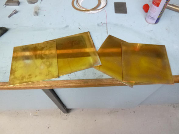

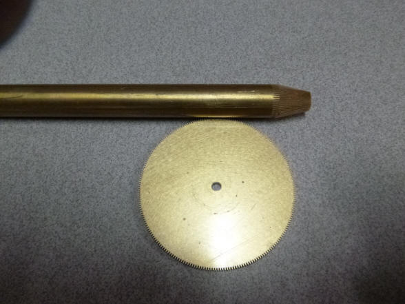
The raw brass plate stock ready to be turned
into a wonderful creation.
Gear cutting is now well underway. The three bullet-shaped parts toward the left-middle of the photo are bevel blanks out of which a bevel wheel will eventually be made.
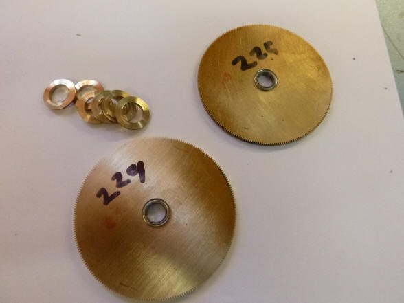
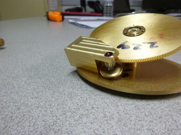
The two large discs are the main differential slant wheels and they are being fitted with their roller bearings. The brass retaining rings are see as well as a close up of both a ring and roller bearing. These slant wheels turn quite slowly and the general rule in this project is where a bearing point turns slower than one revolution per hour and is lightly loaded a dry jewel bearing is used. But here there will be side forces on the wheel as it rotates and a large center arbor to which the wheel is mounted, making a normal jewel impossible. 
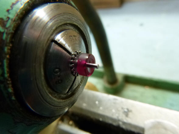
 The first photo shows the compliment of 33 wheel blanks, pinion and other parts. Next a steel bevel pinion blank prior to the machining of the teeth.
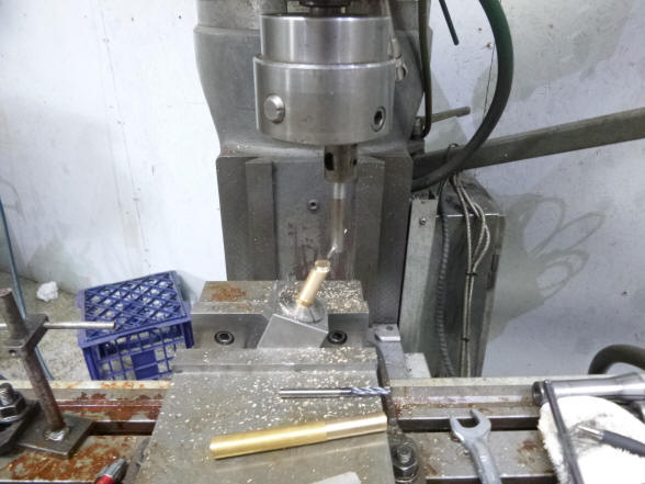
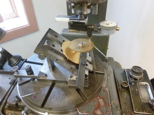
Now the slant wheel mounting arbor is fabricated on the vertical rotary mill. 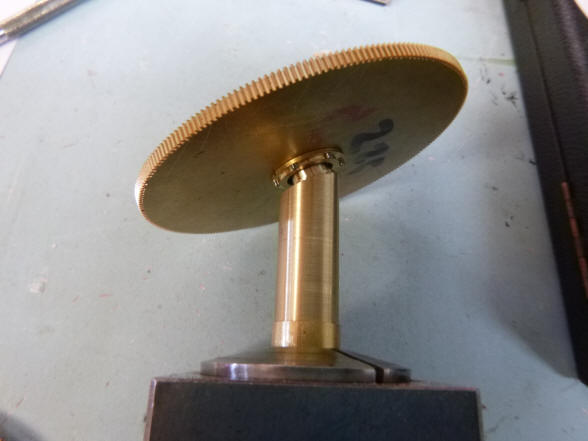
 The first photo shows the slant wheel attached to the mount. The mount will later be slimmed. In the next photo the great anomaly (37 degree tilt) and projection anomaly (23.5 degree tilt) slant wheels comprising part of those differentials for these complications are shown. The models for these based on Antide Janvier's design for differentials that mimic the erratic movements of celestial bodies were illustrated in the November 2016 installment.
In
the first photo the
secondary
pinion and its drive wheel are put together with the
staking tool. Next the jig boring machine is used to check the depthing of
the pinion to the projection slant wheel.
The overall depthing setup on the jig boring machine. Here the secondary drive pinion to the slant wheel for the projection anomaly is tested.
The first photo shows a depthing gauge attached to the boring machine head and the gauge feeler contacting the surface of the slant wheel. Here the wheel is checked for perfect alignment. Next the complex shape needed for the drive wheel cock begins to take shape.
The initial tilted cock is in place with the secondary drive wheel and pinion.
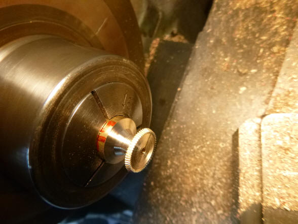
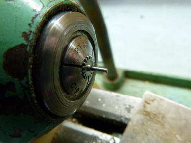
These photos show the
fabrication of a bevel wheel. First is the bevel blank made from brass rod
stock. Next the area is cut down; next the actual dimensions of the bevel
are cut in addition to a bit of counter-sinking of the bevel wheel face.
Finally the wheel is cut off from the brass rod blank and is seen on the
lower left on the tool bed.
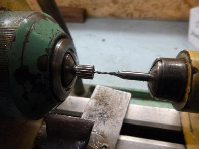
Here are a series of photos showing the steps in
finishing an inserted blue steel pivot. First the pinion is drilled
and then the pivot is pressed in. Then it is rough machined almost to size.
Then it is reduced with a diamond file until the jewel just fits. Then it is
smoothed with a ruby file and finally burnished. The pivot is then filed to
length and the end domed.
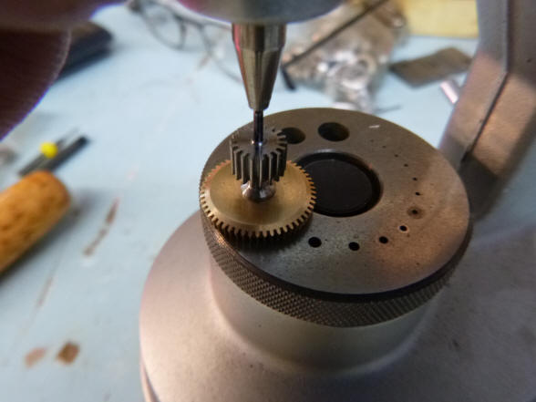
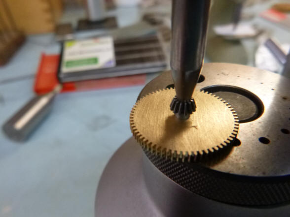
Here again is the
staking tool used to mount a pinion onto its mating drive wheel. This is the
primary drive wheel set which is positioned in the same orientation as the rest of the
surrounding wheel train, where the arbors are horizontal. Next the completed
primary wheel set, held by the tweezers, is shown next to the secondary
mating wheel and pinion. The secondary set is
oriented to the same angle as the large slant wheel. The combination of the
primary and secondary drive wheel sets allows power to change to direction to
that of the slant wheel. |


![]()
![]()
![]()