DISASSEMBLY
The disassembly procedure was approached a bit differently than normal. The movement and strike train had several missing and broken parts and I had never worked on a going train containing a remontoir regulating device; this also being incomplete. I wanted to see if the going train would operate successfully before restoring the frame or strike train so this part of the movement was first removed, cleaned, reassembled and tested. Then I did the same with the strike train. Lastly, I removed both trains and restored the frame followed by the final reassemble of the entire movement. For purposes of simplicity, I have arranged this page as if the disassembly had taken place all at once as is the usual manner.
Click on any image to enlarge.


 1
2
3
4
5
6
7
1
2
3
4
5
6
7


 8
9
10
11
12
13
14
8
9
10
11
12
13
14


15
16
17
18
19
20
21


 22
23
24
25
26
27
28
22
23
24
25
26
27
28


 29
29
30
31
32
33
34
29
29
30
31
32
33
34
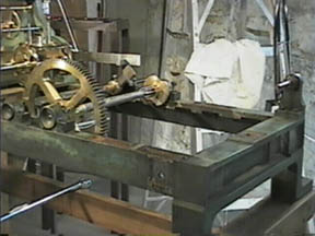
Figure 8 shows the entire remontoir system on the white piece of paper. Notice the wide difference in scale of the bolts in Fig. 22, something not usually seen in a single movement. The weight of the largest wheel in the strike train is 18 lbs.; the smallest in the pilot clock is under 1 oz.
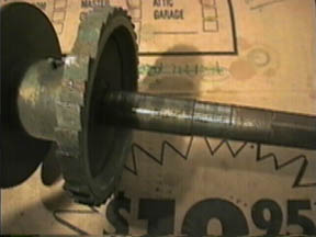
All parts had oil or WD40 applied to them and allowed to sit for a while to allow loosening. Be sure to remove all dirt from slot heads (Fig. 29) to be sure the screwdriver has a good grip. Of all the screws and bolts only two had to be drilled out as the head in one case was missing and the other was too rusted to be of any use. The most difficult system to disassemble, as is usually the case, was the removal of the winding barrel cylinder from its ends.
Figure 11 shows the pilot face removed. Special care was exercised as the glass was a thin doughnut shaped piece held fast by a brass bezel. The numbers were simply painted on paper. The paper itself was somewhat discolored in areas, so no effort was made to restore this - the only part of the clock not restored. I could have photocopied or scanned the old paper face onto a new piece of appropriately colored paper, but I believe this would have looked 'too fake' no matter what I tried.
![]()
![]()
![]()